


6
ED5860 (B) Series
Installation Instructions
Exit Device
FM544 02/20
For installation assistance contact Corbin Russwin
1-800-543-3658 • [email protected]
Copyright © 1998, 2020 ASSA ABLOY Access and Egress Hardware Group, Inc. All rights reserved. Reproduction in whole
or in part without the express written permission of ASSA ABLOY Access and Egress Hardware Group, Inc. is prohibited.
5
Pre-Installation
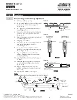
a
To Change Hands
1. Remove four (4) screws and
vertical lifter assembly.
2. Rotate device 180˚ to
opposite orientation.
3. Insert vertical lifter assembly and
reinstall screws.
Note:
Lifter must fit under lift block as
shown. (Figure 3)
b
Check Before Starting
Doors and frames with walls having a structural
thickness (metal skin plus reinforcement) to
engage less than three (3) full screw threads are
considered unreinforced.
Unreinforced Doors:
Use SNB (sex nuts and bolts) or Blind Rivet Nuts.
Unreinforced Frames:
Use Blind Rivet Nuts. (Figure 5)
Recommended fasteners for unreinforced
openings may not be supplied by Corbin Russwin.
• Door must swing freely.
• Door must not be warped.
• Door must not bind.
• Door must not sag.
Blind Rivet Nut
Door Skin
Reinforcement
Figure 4
Figure 5
• Minimum Door
Stile: 4-1/2"
(114mm)
• Door and frame
must meet
structural and
dimensional
specifications
on exit device
template(s) for
door and frame
preparation.
• Device must seat
flush on door
surface. To clear
raised molding,
consult the
factory.
Figure 3
RHR Device
RHR Door
LHR Device
LHR Door
Lift Block
Vertical Lifter Assembly
Vertical Lifter Assembly
(4) 8-32 x 3/16
"
PRHMS
(4) 8-32 x 3/16
"
PRHMS


