
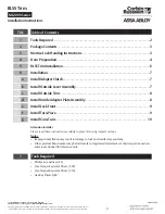


7
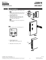
BLSS Trim
Installation Instructions
ML2000 Series
FM351 08/19
Copyright © 2019, ASSA ABLOY Access and Egress Hardware Group, Inc. All rights reserved. Reproduction in whole or
in part without the express written permission of ASSA ABLOY Access and Egress Hardware Group, Inc. is prohibited.
For installation assistance contact Corbin Russwin
1-800-543-3658 • [email protected]
6
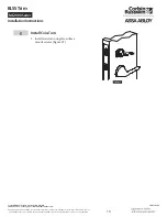
Installation
a
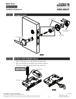
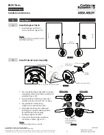
Install Adapter Clutch
1. Install adapter clutch into
mortise lock hub. (Figure 19)
Note:
Adapter clutch is oriented toward
latchbolt as shown.
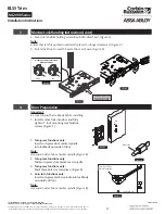
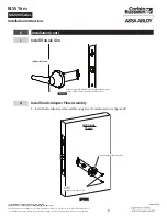
b
Install Outside Lever Assembly
Figure 20
Bushing
(Outside)
Rose/Adapter Plate Assembly
Align rose screw with gap in spring cartridge
Outside Lever Assembly
857F598 Spindle
Apply grease to
these surfaces
1. Use outside bushing and spindle to connect
rose/adapter plate assembly to outside lever
assembly. (Figure 20)
2. Insert spindle into bushing; ensure that
spindle is inserted no more than ¾
"
deep.
3. Use spindle to rotate bushing
clockwise into outside lever hole.
4. Fully tighten bushing, then unthread
bushing just enough to allow spindle to
be inserted into lever, keeping
bushing as tight as possible.
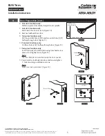
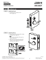
5. Once assembled, spindle orientation
should be as shown. (Figure 21)
Note:
Longer spindle used on outside
Figure 19
857F658
Adapter Clutch
Hinge Side
Hinge Side
Figure 21
Note position
and orientation
of spindles.
RH Outside
LH Outside


