background image

28

ASRock  Z77 Extreme6/TB4  Motherboard


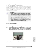
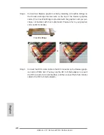
Although you have selected the option “Enable CrossFire

TM

”, the CrossFireX

TM


function may not work actually. Your computer will automatically reboot. After 


restarting your computer, please confirm whether the option “Enable CrossFire

TM

” in 


“AMD Catalyst Control Center” is selected or not; if not, please select it again, and 


then you are able to enjoy the benefits of CrossFireX

TM

.

Step 7.  You can freely enjoy the benefits of CrossFireX

TM

 or Quad CrossFireX

TM

.

 * CrossFireX

TM

 appearing here is a registered trademark of AMD Technologies Inc., and is used 

    only for identification or explanation and to the owners’ benefit, without intent to infringe.

 * For further information of AMD CrossFireX

TM

 technology, please check AMD’s website for 

    updates and details.

English

Содержание TB4

Страница 1: ...ns of merchantability or fitness for a particular purpose In no event shall ASRock its directors officers employees or agents be liable for any indirect special incidental or consequential damages including damages for loss of profits loss of business loss of data interruption of business and the like even if ASRock has been advised of the pos sibility of such damages arising from any defect or er...

Страница 2: ...F Header HDMI_SPDIF1 Black 34 PCI Slot PCI2 Black 35 PCI Express 3 0 x16 Slot PCIE4 Black 36 PCI Slot PCI1 Black 37 PCI Express 2 0 x1 Slot PCIE3 Black 38 PCI Express 3 0 x16 Slot PCIE2 Black 39 PCI Express 2 0 x1 Slot PCIE1 Black 40 SLI XFIRE Power Connector 41 Chassis Fan Connector CHA_FAN2 Intel Z77 DDR3_A2 64 bit 240 pin module DDR3_A1 64 bit 240 pin module DDR3_B2 64 bit 240 pin module DDR3_B...

Страница 3: ...ion 1 PS 2 Keyboard Mouse Port Purple Green 2 DisplayPort Input HDMI_DP_1 3 USB 2 0 Ports USB01 4 LAN RJ 45 Port 5 D Sub Port VGA1 6 Central Bass Orange 7 Rear Speaker Black 8 Line In Light Blue 9 Front Speaker Lime 10 Microphone Pink 11 Optical SPDIF Out Port 12 Thunderbolt Port TBT1 13 Thunderbolt Port TBT2 14 USB 3 0 Ports USB3_23 15 IEEE 1394 Port 1394 16 eSATA3 Connector 17 HDMI Port HDMI1 18...

Страница 4: ... allowed to select Realtek HDA Primary output to use Rear Speaker Central Bass and Front Speaker or select Realtek HDA Audio 2nd output to use front panel audio eSATA3 connector supports SATA Gen3 in cable 1M English If you use 2 channel speaker please connect the speaker s plug into Front Speaker Jack See the table below for connection details in accordance with the type of speaker you use TABLE ...

Страница 5: ...might be updated the content of this manual will be subject to change without no tice In case any modifications of this manual occur the updated version will be available on ASRock website without further notice You may find the latest VGA cards and CPU support lists on ASRock website as well ASRock website http www asrock com If you require technical support related to this motherboard please vis...

Страница 6: ...32GB see CAUTION 3 Supports Intel Extreme Memory Profile XMP 1 3 1 2 Expansion Slots 2 x PCI Express 3 0 x16 slots PCIE2 PCIE4 single at x16 PCIE2 x8 PCIE4 or dual at x8 x8 mode see CAUTION 4 PCIE 3 0 is only supported with Intel Ivy Bridge CPU With Intel Sandy Bridge CPU it only supports PCIE 2 0 2 x PCI Express 2 0 x 1 slots 2 x PCI slots Supports AMD Quad CrossFireXTM and CrossFireXTM Supports ...

Страница 7: ...vices Audio 7 1 CH HD Audio with Content Protection Realtek ALC898 Audio Codec Premium Blu ray audio support Supports THX TruStudioTM LAN PCIE x1 Gigabit LAN 10 100 1000 Mb s Broadcom BCM57781 Supports Wake On LAN Supports Energy Efficient Ethernet 802 3az Supports PXE Rear Panel I O I O Panel 1 x PS 2 Mouse Keyboard Port 1 x D Sub Port 1 x HDMI Port 1 x DisplayPort Input for Thunderbolt port TBT2...

Страница 8: ...rs support RAID RAID 0 RAID 1 RAID 5 RAID 10 Intel Rapid Storage and Intel Smart Response Technology NCQ AHCI and Hot Plug 4 x SATA3 6 0Gb s connectors 1 x IR header 1 x CIR header 1 x COM port header 1 x HDMI_SPDIF header 1 x IEEE 1394 header 1 x Power LED header 2 x CPU Fan connectors 1 x 4 pin 1 x 3 pin 3 x Chassis Fan connectors 1 x 4 pin 2 x 3 pin 1 x Power Fan connector 3 pin 24 pin ATX powe...

Страница 9: ...y with processors which are GPU integrated ASRock OMG Online Management Guard see CAUTION 18 ASRock Internet Flash see CAUTION 19 ASRock UEFI System Browser ASRock Dehumidfier Function see CAUTION 20 ASRock Fast Boot ASRock Restart to UEFI Hybrid Booster CPU Frequency Stepless Control see CAUTION 21 ASRock U COP see CAUTION 22 Boot Failure Guard B F G Good Night LED Hardware CPU Chassis Temperatur...

Страница 10: ...tors cannot be enabled at the same time 7 xvYCC and Deep Color are only supported under Windows 8 64 bit 8 7 64 bit 7 Deep Color mode will be enabled only if the display supports 12bpc in EDID HBR is supported under Windows 8 64 bit 8 7 64 bit 7 VistaTM 64 bit VistaTM 8 For microphone input this motherboard supports both stereo and mono modes For audio output this motherboard supports 2 channel 4 ...

Страница 11: ... lution for you ASRock APP Charger Simply install the APP Charger driver it makes your iPhone charge much quickly from your computer and up to 40 faster than before ASRock APP Charger allows you to quickly charge many Apple devices simultaneously and even supports continuous charging when your PC enters into Standby mode S1 Sus pend to RAM S3 hibernation mode S4 or power off S5 With APP Charger dr...

Страница 12: ...ance by intelligently re ducing redundant rendering tasks in the flow between the CPU GPU and the display 18 Administrators are able to establish an internet curfew or restrict internet access at specified times via OMG You may schedule the starting and ending hours of internet access granted to other users In order to pre vent users from bypassing OMG guest accounts without permission to modify t...

Страница 13: ...he completed system According to EuP the total AC power of the completed system should be under 1 00W in off mode condition To meet EuP standards an EuP ready motherboard and an EuP ready power supply are required According to Intel s suggestion the EuP ready power supply must meet the standard of 5v and the standby power efficiency should be higher than 50 under 100 mA current consumption For EuP...

Страница 14: ... you and damages to motherboard components 2 In order to avoid damage from static electricity to the motherboard s components NEVER place your motherboard directly on a carpet Also remember to use a grounded wrist strap or touch a safety grounded object before you handle the components 3 Hold components by the edges and do not touch the ICs 4 Whenever you uninstall any components place them on a g...

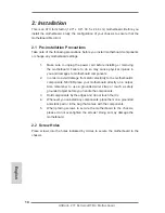
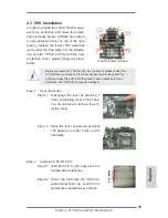
Страница 15: ...lease check if the CPU surface is unclean or if there are any bent pins in the socket Do not force to insert the CPU into the socket if above situation is found Otherwise the CPU will be seriously damaged Step 1 Open the socket Step 1 1 Disengage the lever by pressing it down and sliding it out of the hook You do not have to remove the pro tection cover Step 1 2 Keep the lever positioned at about ...

Страница 16: ...CPU is within the sock et and properly mated to the orient keys Step 3 Close the socket Step 3 1 Flip the load plate onto the IHS Step 3 2 Press down the load lever and se cure it with the load plate tab under the retention tab The protection cover will automatically come off by itself Please save and replace the cover if the processor is removed The cover must be placed if you wish to return the ...

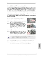
Страница 17: ...Below is an example to illustrate the installation of the heatsink for 1155 Pin CPUs Step 1 Apply thermal interface material onto the cen ter of the IHS on the socket s surface Step 2 Place the heatsink onto the socket Ensure that the fan cables are faced on the side clos est to the CPU fan connector on the mother board CPU_FAN1 see p 2 No 3 or CPU_ FAN3 see p 2 No 4 Step 3 Align fasteners with th...

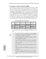
Страница 18: ...ted Populated 3 Populated Populated Populated Populated For configuration 3 please install identical DDR3 DIMMs in all four slots 1 If you want to install two memory modules for optimal compatibility and reliability it is recommended to install them in the slots DDR3_ A1 and DDR3_B1 or DDR3_A2 and DDR3_B2 2 If only one memory module or three memory modules are installed in the DDR3 DIMM slots on t...

Страница 19: ...utward Step 2 Align a DIMM on the slot such that the notch on the DIMM matches the break on the slot The DIMM only fits in one correct orientation It will cause permanent damage to the motherboard and the DIMM if you force the DIMM into the slot in incorrect orientation Step 3 Firmly insert the DIMM into the slot until the retaining clips at both ends fully snap back in place and the DIMM is prope...

Страница 20: ...PCIE2 will work at x8 bandwidth while PCIE4 works at x8 bandwidth 3 Please connect a chassis fan to the motherboard s chassis fan connector CHA_FAN1 CHA_FAN2 or CHA_FAN3 when using multiple graphics cards for better thermal environment 4 Only PCIE2 and PCIE4 slots support Gen 3 speed To run the PCI Express in Gen 3 speed please install an Ivy Bridge CPU If you install a Sandy Bridge CPU the PCI Ex...

Страница 21: ...en the GPU chips version shall be the same Insert one graphics card into PCIE2 slot and the other graphics card to PCIE4 slot Make sure that the cards are properly seated on the slots Step2 If required connect the auxiliary power source to the PCI Express graphics cards Requirements 1 For SLITM technology you should have two identical SLITM ready graphics cards that are NVIDIA certified For Quad S...

Страница 22: ... the monitor connector or the DVI connector of the graphics card that is inserted into PCIE2 slot Step3 Align and insert the ASRock SLI_Bridge_2S Card to the goldfingers on each graphics card Make sure the ASRock SLI_Bridge_2S Card is firmly in place ASRock SLI_Bridge_2S Card English ...

Страница 23: ...ase follow the below procedures to enable the multi GPU feature For Windows XP XP 64 bit OS For SLITM mode only A Double click NVIDIA Settings icon on your Windows taskbar B From the pop up menu select Set SLI and PhysX configuration In Set PhysX GPU acceleration item please select Enabled In Select an SLI configuration item please select Enable SLI And click Apply C Reboot your system D You can f...

Страница 24: ...and Quad SLITM mode A Click the Start icon on your Windows taskbar B From the pop up menu select All Programs and then click NVIDIA Corporation C Select NVIDIA Control Panel tab D Select Control Panel tab E From the pop up menu select Set SLI and PhysX configuration In Set PhysX GPU acceleration item please select Enabled In Select an SLI configuration item please select Enable SLI And click Apply...

Страница 25: ...CrossFireXTM Ready Graphics Cards Different CrossFireXTM cards may require different methods to enable CrossFireXTM feature For other CrossFireXTM cards that AMD has released or will release in the future please refer to AMD graphics card manuals for detailed installation guide Step 1 Insert one Radeon graphics card into PCIE2 slot and the other Radeon graphics card to PCIE4 slot Make sure that th...

Страница 26: ...nnector to D Sub interface and then connect the D Sub monitor cable to the DVI to D Sub adapter Step 2 Connect two Radeon graphics cards by installing a CrossFire Bridge on the CrossFire Bridge Interconnects on the top of the Radeon graphics cards The CrossFire Bridge is provided with the graphics card you pur chase not bundled with this motherboard Please refer to your graphics card vendor for de...

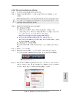
Страница 27: ...nstalled prior to downloading and installing the CATALYST Control Center Please check Microsoft s website for details For Windows 8 7 VistaTM OS Install the CATALYST Control Center Please check AMD s website for de tails Step 4 Restart your computer Step 5 Install the VGA card drivers to your system and restart your computer You will find AMD Catalyst Control Center on your Windows taskbar AMD Cat...

Страница 28: ...l Center is selected or not if not please select it again and then you are able to enjoy the benefits of CrossFireXTM Step 7 You can freely enjoy the benefits of CrossFireXTM or Quad CrossFireXTM CrossFireXTM appearing here is a registered trademark of AMD Technologies Inc and is used only for identification or explanation and to the owners benefit without intent to infringe For further informatio...

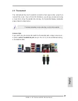
Страница 29: ...we strongly recommend using a 64 bit OS to bring ThunderBolt into full play For thunderbolt display installation please follow the steps below Thunderbolt cables are provided by your monitor supplier Internal VGA If you want to use the internal VGA with the Thunderbolt ports simply connect your monitor to either Thunderbolt port see p 3 No 12 13 on the motherboard using a Thunderbolt cable ...

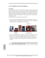
Страница 30: ... easily enjoy the benefits of dual monitor without in stalling any add on VGA cards to this motherboard This motherboard also provides independent display controllers for D Sub HDMI and Thunderbolt to support dual VGA output so that the D Sub HDMI and Thunderbolt can drive the same or differ ent display contents To enable dual monitor please follow the steps below 1 Connect a D Sub monitor cable t...

Страница 31: ...e system memory If you do not adjust the UEFI setup the default value of Share Memory Auto will disable D Sub function when an add on VGA card is inserted to this motherboard 4 Install the onboard VGA driver and the add on PCI Express VGA card driver to your system If you have installed the drivers already there is no need to install them again 5 Set up a multi monitor display For Windows XP XP 64...

Страница 32: ...ore you can enjoy the superior display quality with high definition HDCP encryption contents Please refer to the instructions below for more details about HDCP What is HDCP HDCP stands for High Bandwidth Digital Content Protection a specification developed by Intel for protecting digital entertainment content that uses the DVI interface HDCP is a copy protection scheme to eliminate the possibility...

Страница 33: ... and the CIR header Please make sure the wire assignments and the pin assignments are matched correctly USB_PWR P P GND ATX 5VSB IRRX IRTX GND DUMMY Step3 Install the Multi Angle CIR Receiver to the front USB port Step4 Boot up your system Press F2 or Del to enter the BIOS Setup Utility Make sure the option CIR Controller is set to Enabled Advanced Super IO Configuration CIR Controller Enabled If ...

Страница 34: ... other ports will remain USB ports 2 The Multi Angle CIR Receiver is used for the front USB only Please do not use the rear USB bracket to connect it on the rear panel The Multi Angle CIR Receiver can receive multi directional infrared signals top down and front which is compatible with most of the chassis on the market 3 The Multi Angle CIR Receiver does not support Hot Plug Please install it bef...

Страница 35: ...em parameters to default setup please turn off the computer and unplug the power cord from the power supply After waiting for 15 seconds use a jumper cap to short pin2 and pin3 on CLRCMOS1 for 5 seconds However please do not clear the CMOS right after you update the BIOS If you need to clear the CMOS when you just finish updating the BIOS you must boot up the system first and then shut it down bef...

Страница 36: ...se four Serial ATA3 SATA3 SATA3_A1_A2 see p 2 No 11 connectors support SATA data SATA3_0_1 see p 2 No 12 cables for internal storage devices The current SATA3 interface allows up to 6 0 Gb s data transfer rate If the eSATA3 port on the rear I O has been connected the internal SATA3_A2 will not funtion Serial ATA SATA Either end of the SATA data Data Cable cable can be connected to the Optional SAT...

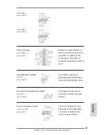
Страница 37: ...can support two USB 3 0 ports Infrared Module Header This header supports an 5 pin IR1 optional wireless transmitting see p 2 No 30 and receiving infrared module Consumer Infrared Module Header This header can be used to 4 pin CIR1 connect the remote controller see p 2 No 28 receiver Front Panel Audio Header This is an interface for front 9 pin HD_AUDIO1 panel audio cable that allows see p 2 No 32...

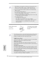
Страница 38: ...accommodates 9 pin PANEL1 several system front panel see p 2 No 20 functions Connect the power switch reset switch and system status indicator on the chassis to this header according to the pin assignments below Note the positive and negative pins before connecting the cables PWRBTN Power Switch Connect to the power switch on the chassis front panel You may configure the way to turn off your syste...

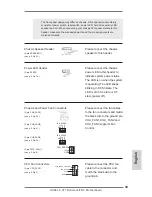
Страница 39: ...ader to see p 2 No 18 indicate system power status The LED is on when the system is operating The LED keeps blinking in S1 S3 state The LED is off in S4 state or S5 state power off Chassis and Power Fan Connectors Please connect the fan cables 4 pin CHA_FAN1 to the fan connectors and match see p 2 No 23 the black wire to the ground pin CHA_FAN1 CHA_FAN2 and 3 pin CHA_FAN2 CHA_FAN3 supports Fan see...

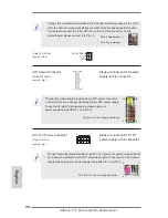
Страница 40: ... 8 pin ATX12V1 power supply to this connector see p 2 No 1 4 Pin ATX 12V Power Supply Installation Though this motherboard provides 8 pin ATX 12V power connector it can still work if you adopt a traditional 4 pin ATX 12V power supply To use the 4 pin ATX power supply please plug your power supply along with Pin 1 and Pin 5 8 5 4 1 Though this motherboard provides 4 Pin CPU fan Quiet Fan support th...

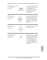
Страница 41: ...1394 9 pin FRONT_1394 port on the I O panel there is see p 2 No 19 one IEEE 1394 header on this motherboard This IEEE 1394 header can support one IEEE 1394 port Serial port Header This COM1 header supports a 9 pin COM1 serial port module see p 2 No 31 HDMI_SPDIF Header HDMI_SPDIF header providing 2 pin HDMI_SPDIF1 SPDIF audio output to HDMI see p 2 No 33 VGA card allows the system to connect HDMI ...

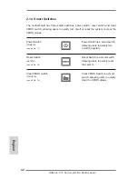
Страница 42: ...witch RSTBTN allowing users to quickly reset see p 2 No 16 the system Clear CMOS Switch Clear CMOS Switch is a smart CLRCBTN switch allowing users to quickly see p 3 No 18 clear the CMOS values 2 14 Smart Switches The motherboard has three smart switches power switch reset switch and clear CMOS switch allowing users to quickly turn on off or reset the system to clear the CMOS values English ...

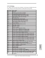
Страница 43: ...ation CPU module specific 0x15 Pre memory North Bridge initialization is started 0x16 Pre Memory North Bridge initialization North Bridge module specific 0x17 Pre Memory North Bridge initialization North Bridge module specific 0x18 Pre Memory North Bridge initialization North Bridge module specific 0x19 Pre memory South Bridge initialization is started 0x1A Pre memory South Bridge initialization S...

Страница 44: ...Unspecified memory initialization error 0x55 Memory not installed 0x56 Invalid CPU type or Speed 0x57 CPU mismatch 0x58 CPU self test failed or possible CPU cache error 0x59 CPU micro code is not found or micro code update is failed 0x5A Internal CPU error 0x5B reset PPI is not available 0x5C 0x5F Reserved for future AMI error codes 0xE0 S3 Resume is stared S3 Resume PPI is called by the DXE IPL 0...

Страница 45: ...devices initialization 0x73 South Bridge DXE Initialization South Bridge module specific 0x74 South Bridge DXE Initialization South Bridge module specific 0x75 South Bridge DXE Initialization South Bridge module specific 0x76 South Bridge DXE Initialization South Bridge module specific 0x77 South Bridge DXE Initialization South Bridge module specific 0x78 ACPI module initialization 0x79 CSM initia...

Страница 46: ...M 0xB7 Configuration Reset reset of NVRAM settings 0xB8 0xBF Reserved for future AMI codes 0xC0 0xCF OEM BDS initialization codes 0xD0 CPU initialization error 0xD1 North Bridge initialization error 0xD2 South Bridge initialization error 0xD3 Some of the Architectural Protocols are not available 0xD4 PCI resource allocation error Out of Resources 0xD5 No Space for Legacy Option ROM 0xD6 No Console...

Страница 47: ...cedures RAID Installation Guide 2 18 Installing Windows 8 8 64 bit 7 7 64 bit VistaTM VistaTM 64 bit XP XP 64 bit Without RAID Functions If you want to install Windows 8 8 64 bit 7 7 64 bit VistaTM VistaTM 64 bit XP XP 64 bit OS on your SATA SATA2 SATA3 HDDs without RAID functions please follow the procedures below according to the OS you install 2 18 1 Installing Windows XP XP 64 bit Without RAID...

Страница 48: ...option SATA Mode Selection to AHCI For SATA2_2 to SATA2_5 SATA3_0 and SATA3_1 ports Set the option ASMedia SATA3 Mode to AHCI For SATA3_A1 and SATA3_A2 ports STEP 2 Install Windows 8 8 64 bit 7 7 64 bit VistaTM VistaTM 64 bit OS on your system Using SATA SATA2 SATA3 HDDs without NCQ function STEP 1 Set Up UEFI A Enter UEFI SETUP UTILITY Advanced screen Storage Configuration B Set the option SATA M...

Страница 49: ... various sub menus and to select among the prede termined choices For the detailed information about BIOS Setup please refer to the User Manual PDF file contained in the Support CD 4 Software Support CD information This motherboard supports various Microsoft Windows operating systems 8 8 64 bit 7 7 64 bit VistaTM VistaTM 64 bit The Support CD that came with the motherboard contains necessary drive...

Страница 50: ... der Inhalt dieses Handbuches ebenfalls jederzeit geändert werden Für den Fall dass sich Änderungen an diesem Handbuch ergeben wird eine neue Version auf der ASRock Website ohne weitere Ankündigung verfügbar sein Die neuesten Grafikkarten und unterstützten CPUs sind auch auf der ASRock Website aufgelistet ASRock Website http www asrock com Wenn Sie technische Unterstützung zu Ihrem Motherboard ode...

Страница 51: ...t des Systemspeichers 32GB Unterstützt Intel Extreme Memory Profile XMP 1 3 1 2 Erweiterungs 2 x PCI Express 3 0 x16 Steckplätze PCIE2 PCIE4 Einzeln steckplätze bei x16 PCIE2 x8 PCIE4 oder dual im x8 x8 Modus PCIE 3 0 wird nur mit Intel Ivy Bridge Prozessor unterstützt Mit Intel Sandy Bridge Prozessor wird nur PCIE 2 0 unterstützt 2 x PCI Express 2 0 x1 Steckplätze 2 x PCI Steckplätze Unterstützt ...

Страница 52: ... Verbindungen mit bis zu 6 Thunderbolt Geräten Audio 7 1 CH HD Audio mit dem Inhalt Schutz Realtek ALC898 Audio Codec Premium Blu ray Audio Unterstützung Unterstützt THX TruStudioTM LAN PCIE x1 Gigabit LAN 10 100 1000 Mb s Broadcom BCM57781 Unterstützt Wake On LAN Unterstützt energieeffizientes Ethernet 802 3az Unterstützt PXE E A Anschlüsse 1 x PS 2 Mausanschluss Tastaturanschluss an der Rückseit...

Страница 53: ...lüsse 4 x SATA2 3 0 GB s Anschlüsse unterstützen RAID RAID 0 RAID 1 RAID 5 RAID 10 Intel Rapid Storage und Intel Smart Response Technologie NCQ AHCI und Hot Plug 4 x SATA3 6 0 GB s Anschlüsse 1 x Infrarot Modul Header 1 x Consumer Infrared Modul Header 1 x COM Anschluss Header 1 x HDMI_SPDIF Anschluss 1 x IEEE 1394 Anschluss 1 x Betriebs LED Header 2 x CPUlüfter Anschlüsse 1 x 4 pin 1 x 3 pin 3 x ...

Страница 54: ...ung 12V 5V 3 3V Vcore Betriebssysteme Unterstützt Microsoft Windows 8 8 64 bit 7 7 64 Bit VistaTM VistaTM 64 Bit XP XP 64 Bit Zertifizierungen FCC CE WHQL Gemäß Ökodesign Richtlinie ErP EuP Stromversorgung gemäß Ökodesign Richtlinie ErP EuP erforderlich Für die ausführliche Produktinformation besuchen Sie bitte unsere Website http www asrock com WARNUNG Beachten Sie bitte dass Overclocking einschl...

Страница 55: ...tzen der Systemparameter auf die Standardeinrichtung schalten Sie den Computer bitte aus und trennen das Netzkabel von der Stromversorgung Warten Sie 15 Sekunden schließen Sie dann Pin2 und Pin3 am CLRCMOS1 über einen Jumper fünf Sekunden lang kurz Sie sollten das CMOS allerdings nicht direkt nach der BIOS Aktualisierung löschen Wenn Sie das CMOS nach Abschluss der BIOS Aktualisierung löschen müss...

Страница 56: ... SATA3 Schnittstelle ermöglicht eine Datenübertragungsrate bis 6 0 Gb s Falls der eSATA Port an der Rückblende verbunden wurde funktioniert der interne SATA3_A2 Anschluss nicht 1 4 Integrierte Header und Anschlüsse Integrierte Header und Anschlüsse sind KEINE Jumper Setzen Sie KE INE Jumperkappen auf diese Header und Anschlüsse Wenn Sie Jump erkappen auf Header und Anschlüsse setzen wird das Mothe...

Страница 57: ... S 2 No 26 9 pol USB_6_7 siehe S 2 No 27 USB 3 0 Header Neben vier Standard USB 19 pol USB3_4_5 3 0 Ports am E A Panel siehe S 2 No 8 befindet sich ein USB 3 0 Header an diesem Motherboard Dieser USB 3 0 Header kann zwei USB 3 0 Ports unterstützen Infrarot Modul Header Dieser Header unterstützt ein 5 pin IR1 optionales drahtloses Sende siehe S 2 No 30 und Empfangs Infrarotmodul Consumer Infrared M...

Страница 58: ...ind nur für den HD Audioanschluss gedacht Diese Anschlüsse müssen nicht an die AC 97 Audioleiste angeschlossen werden E So aktivieren Sie das Mikrofon an der Vorderseite Bei den Betriebssystemen Windows XP XP 64 Bit Wählen Sie Mixer Wählen Sie Recorder Rekorder Klicken Sie dann auf FrontMic Vorderes Mikrofon Bei den Betriebssystemen Windows 8 8 64 Bit 7 7 64 Bit VistaTM VistaTM 64 Bit Wählen Sie i...

Страница 59: ... leuchtet wenn die Festplatte Daten liest oder schreibt Das Design der Frontblende kann je nach Gehäuse variiere Ein Frontblendenmodul besteht hauptsächlich aus einer Ein Austaste einer Reset Taste einer Betriebs LED einer Festplattenaktivitäts LED Lautsprechern etc Stellen Sie beim Anschließen des Frontblendenmoduls Ihres Gehäuses an diesem Header sicher dass die Kabel und Pinbelegung korrekt übe...

Страница 60: ... schwarzen Draht dem Erdungsstift an Obwohl dieses Motherboard einen vierpoligen CPU Lüfteranschluss Quiet Fan bietet können auch CPU Lüfter mit dreipoligem Anschluss angeschlossen werden auch ohne Geschwindigkeitsregulierung Wenn Sie einen dreipoligen CPU Lüfter an den CPU Lüferanschluss dieses Motherboards anschließen möchten verbinden Sie ihn bitte mit den Pins 1 3 Pins 1 3 anschließen Lüfter m...

Страница 61: ...8 5 Installation der 4 Pin ATX 12V Energieversorgung Obwohl diese Hauptplatine 8 Pin ATX 12V Stromanschluss zur Verfügung stellt kann sie noch arbeiten wenn Sie einen traditionellen 4 Pin ATX 12V Energieversorgung adoptieren Um die 4 Pin ATX Energieversorgung zu verwenden stecken Sie bitte Ihre Energieversorgung zusammen mit dem Pin 1 und Pin 5 ein 8 5 4 1 SLI XFIRE Stromanschluss Sie müssen diese...

Страница 62: ... an das System Bitte verbinden Sie den HDMI_SPDIF Anschluss der HDMI VGA Karte mit diesem Anschluss COM Anschluss Header Dieser COM Anschluss Header 9 pin COM1 wird verwendet um ein siehe S 2 No 31 COM Anschlussmodul zu unterstützen IEEE 1394 Header Außer einem vorgegebenem 9 pin FRONT_1394 IEEE 1394 Port auf dem Ein siehe S 4 No 19 Ausgabe Paneel gibt es einen IEEE 1394 Header FRONT_1394 auf dies...

Страница 63: ...löschen können Netzschalter Der Netzschalter ist ein PWRBTN Schnellschalter mit dem siehe S 2 No 17 Benutzer das System schnell ein ausschalten können Rücksetzschalter Reset Der Rücksetzschalter Reset RSTBTN ist ein Schnellschalter mit dem siehe S 2 No 16 Benutzer das System schnell zurücksetzen können CMOS löschen Schalter Der CMOS löschen Schalter ist CLRCBTN ein Schnellschalter mit dem siehe S ...

Страница 64: ...etaillierte Informationen zum BIOS Setup siehe bitte das Benutzerhandbuch PDF Datei auf der Support CD 3 Software Support CD information Dieses Motherboard unterstützt eine Reiche von Microsoft Windows Betriebssy stemen 8 8 64 Bit 7 7 64 Bit VistaTM VistaTM 64 Bit Die Ihrem Motherboard beigefügte Support CD enthält hilfreiche Software Treiber und Hilfsprogramme mit denen Sie die Funktionen Ihres M...

Страница 65: ...enu de ce manuel est sujet à des changements sans notification Au cas où n importe qu elle modification intervenait sur ce manuel la version mise à jour serait disponible sur le site web ASRock sans nouvel avis Vous trouverez les listes de prise en charge des cartes VGA et CPU également sur le site Web ASRock Site web ASRock http www asrock com Si vous avez besoin de support technique en relation ...

Страница 66: ...IMM DDR3 Supporter DDR3 2800 OC 2400 OC 2133 OC 1866 OC 1600 1333 1066 non ECC sans amortissement mémoire Capacité maxi de mémoire système 32GB Prend en charge le profil de mémoire extrême Intel XMP 1 3 1 2 Slot d extension 2 x slots PCI Express 3 0 x16 PCIE2 PCIE4 simple à x16 PCIE2 x8 PCIE4 ou double en mode x8 x8 PCIE 3 0 n est pris en charge qu avec le processeur Intel Ivy Bridge Avec le proce...

Страница 67: ...D DVD avec HDMI Prend en charge le transfert de données jusqu à 10Gbps via port Thunderbolt Prend en charge jusqu à 6 appareils Thunderbolt via connexion en guirlande Audio 7 1 CH HD Audio avec protection de contenu Realtek ALC898 Audio Codec Prise en charge de l audio Premium Blu ray Prend en charge THX TruStudioTM LAN PCIE x1 Gigabit LAN 10 100 1000 Mb s Broadcom BCM57781 Support du Wake On LAN ...

Страница 68: ... ports USB 3 0 par Intel Z77 prend en charge USB 1 1 2 0 3 0 jusqu à 5Gb s Connecteurs 4 x connecteurs SATA2 3 0 Gb s prennent en charge RAID RAID 0 RAID 1 RAID 5 RAID 10 Intel Rapid Storage et Intel Smart Response NCQ AHCI et Hot Plug 4 x connecteurs SATA3 6 0 Gb s 1 x En tête du module infrarouge 1 x Barrette pour module à infrarouges grand public 1 x En tête de port COM 1 x Connecteur HDMI_SPDI...

Страница 69: ...omatique de la vitesse du ventilateur pour châssis selon la température de l unité centrale Commande de ventilateur CPU Châssis à plusieurs vitesses Monitoring de la tension 12V 5V 3 3V Vcore OS Microsoft Windows 8 8 64 bit 7 7 64 bit VistaTM VistaTM 64 bit XP XP 64 bit Certifications FCC CE WHQL Prêt pour ErP EuP alimentation Prêt pour ErP EuP requise Pour de plus amples informations sur les prod...

Страница 70: ...lez éteindre l ordinateur et débrancher le cordon d alimentation de la prise de courant Après 15 secondes utilisez un couvercle de jumper pour court circuiter les broches pin2 et pin3 de CLRCMOS1 pendant 5 secondes Veuillez cependant ne pas effacer le CMOS immédiatement après avoir mis à jour le BIOS Si vous avez besoin d effacer le CMOS après avoir mis à jour le BIOS vous devez allumer en premier...

Страница 71: ...ce SATA3 actuelle permet des taux transferts de données pouvant aller jusqu à 6 0 Gb s Si le port eSATA sur le panneau E S arrière est utilisé le SATA3_A2 interne ne fonctionnera pas 1 4 En têtes et Connecteurs sur Carte Les en têtes et connecteurs sur carte NE SONT PAS des cavaliers NE PAS placer les capuchons de cavalier sur ces en têtes et con necteurs Le fait de placer les capuchons de cavalie...

Страница 72: ...27 En tête USB 3 0 En plus des quatre ports USB USB3_4_5 br 19 3 0 par défaut sur le panneau voir p 2 No 8 E S il y a une barrette USB 3 0 sur la carte mère Cette barrette USB 3 0 peut prendre en charge deux ports USB 3 0 En tête du module infrarouge Cet en tête supporte un module IR1 br 5 infrarouge optionnel de transfert voir p 2 No 30 et de réception sans fil Barrette pour module à infrarouges ...

Страница 73: ... Ground GND D MIC_RET et OUT_RET sont réservés au panneau audio HD Vous n avez pas besoin de les connecter pour le panneau audio AC 97 E Pour activer le micro avant Pour les systèmes d exploitation Windows XP XP 64 bits Sélectionnez Mixer Sélectionnez Recorder Enregistreur Puis cliquez sur FrontMic Micro avant Pour les systèmes d exploitation Windows 8 8 64 bits 7 7 64 bits VistaTM VistaTM 64 bits...

Страница 74: ... il est éteint S5 HDLED DEL activité du disque dur Connectez ici le voyant DEL d activité du disque dur sur le panneau avant du châssis Ce voyant DEL est allumé lorsque le disque dur est en train de lire ou d écrire des données Le design du panneau avant peut varier en fonction du châssis Un module de panneau avant consiste principalement en interrupteur d alimentation interrupteur de réinitialisa...

Страница 75: ...ère veuillez le connecter aux broches 1 3 CPU_FAN2 br 3 voir p 2 No 4 Installation de ventilateur à 3 broches Broches 1 3 connectées Connecteur pour châssis et ventilateur Branchez les câbles du CHA_FAN1 br 4 ventilateur aux connecteurs voir p 2 No 23 pour ventilateur et faites correspondre le fil noir à la CHA_FAN2 br 3 broche de terre CHA_FAN1 voir p 2 No 41 CHA_FAN2 et CHA_FAN3 prennent en char...

Страница 76: ...d alimentation SLI XFIRE Il n est pas nécessaire d utiliser SLI XFIRE_POWER1 br 4 ce connecteur mais veuillez le voir p 2 No 40 brancher avec un connecteur d alimentation pour disques durs quand deux cartes graphiques sont branchées sur cette carte mère en même temps SLI XFIRE_POWER1 Bien que cette carte mère fournisse un connecteur de courant ATX 24 broches elle peut encore fonctionner si vous ad...

Страница 77: ...module de port COM Connecteur HDMI_SPDIF Connecteur HDMI_SPDIF HDMI_SPDIF1 2 pin fournissant une sortie audio voir p 2 No 33 SPDIF vers la carte VGA HDMI et permettant au système de se connecter au un téléviseur numérique HDMI un projecteur un périphérique LCD Veuillez brancher le connecteur HDMI_SPDIF de la carte VGA HDMI sur ce connecteur Français ...

Страница 78: ... Interrupteur d alimentation PWRBTN voir p 2 No 17 L interrupteur d effacement de CMOS est un interrupteur rapide qui permet à l utilisateur d effacer rapidement les valeurs du CMOS Interrupteur de réinitialisation RSTBTN voir p 2 No 16 Interrupteur d effacement de CMOS CLRCBTN voir p 3 No 18 L interrupteur d alimentation est un interrupteur rapide qui permet à l utilisateur d allumer éteindre rap...

Страница 79: ... vous permet de faire défiler par ses divers sous menus et de choisir parmi les choix prédéterminés Pour des informations détaillées sur le BIOS veuillez consulter le Guide de l utilisateur fichier PDF dans le CD technique 3 Informations sur le CD de support Cette carte mère supporte divers systèmes d exploitation Microsoft Windows 8 7 64 bits 8 7 64 bits VistaTM VistaTM 64 bits Le CD technique li...

Страница 80: ...ere aggiornati pertanto il contenuto di questo manuale può subire variazioni senza preavviso Nel caso in cui questo manuale sia modificato la versione aggiornata sarà disponibile sul sito di ASRock senza altro avviso Sul sito ASRock si possono anche trovare le più recenti schede VGA e gli elenchi di CPU supportate ASRock website http www asrock com Se si necessita dell assistenza tecnica per quest...

Страница 81: ...i Intel XMP Extreme Memory Profile 1 3 1 2 Slot di 2 x Alloggio PCI Express 3 0 x16 PCIE2 PCIE4 singolo in espansione modalità x16 PCIE2 x8 PCIE4 o doppio in modalità x8 x8 PCIE 3 0 è supportato soltanto con la CPU Intel Ivy Bridge Con la CPU Intel Sandy Bridge supporta solamente PCIE 2 0 2 x Alloggio PCI Express 2 0 x1 2 x Alloggio PCI Supporto di AMD Quad CrossFireXTM e CrossFireXTM Supporto di ...

Страница 82: ...LAN PCIE x1 Gigabit LAN 10 100 1000 Mb s Broadcom BCM57781 Supporta Wake On LAN Supporto di Energy Efficient Ethernet 802 3az Supporta PXE Pannello 1 x porta PS 2 per mouse tastiera posteriore I O 1 x porta D Sub 1 x porta HDMI 1 x Ingresso porta di visualizzazione per porta Thunderbolt TBT2 Solo le per prove 2 x porteThunderbolt 1 x porta ottica SPDIF Out 2 x porte USB 2 0 già integrate 1 x conne...

Страница 83: ...ore modulo infrarosso consumer 1 x collettore porta COM 1 x connettore HDMI_SPDIF 1 x collettore IEEE 1394 1 x LED di accensione 2 x connettori CPU ventola 1 x 4 pin 1 x 3 pin 3 x connettori Chassis ventola 1 x 4 pin 2 x 3 pin 1 x connettore Alimentazione ventola 3 pin 24 pin collettore alimentazione ATX 8 pin connettore ATX 12V Collettore alimentazione SLI XFIRE Connettore audio sul pannello fron...

Страница 84: ...M VistaTM SO 64 bit XP XP 64 bit Certificazioni FCC CE WHQL Predisposto ErP EuP è necessaria l alimentazione predisposta per il sistema ErP EuP Per ulteriori informazioni prego visitare il nostro sito internet http www asrock com AVVISO Si prega di prendere atto che la procedura di overclocking implica dei rischi come anche la regolazione delle impostazioni del BIOS l applicazione della tecnologia...

Страница 85: ...gurazione iniziale spegnere il computer e scollegare il cavo d alimentazione dalla presa di corrente Attendere 15 secondi poi usare un cappuccio jumper per cortocircuitare il pin 2 ed il pin 3 su CLRCMOS1 per 5 secondi Tuttavia si consiglia di non cancellare la CMOS subito dopo avere aggiornato il BIOS Se si deve azzerare la CMOS quando si è completato l aggiornamento del BIOS è necessario per pri...

Страница 86: ...ni L interfaccia SATA2 attuale permette velocità di trasferimento dati fino a 3 0 Gb s Serial ATA3 Connectors Questi quattro connettori Serial SATA3_A1_A2 vedi p 2 Nr 11 ATA3 SATA3 supportano cavi SATA3_0_1 vedi p 2 Nr 12 dati SATA per dispositivi di immagazzinamento interni L interfaccia SATA3 attuale permette velocità di trasferimento dati fino a 6 0 Gb s Se si è collegata la porta eSATA sull I ...

Страница 87: ...i p 2 Nr 27 Collettore USB 3 0 Oltre alle quattro porte USB 3 0 19 pin USB3_4_5 standard del pannello I O vedi p 2 Nr 8 questa scheda madre è dotata di un header USB 3 0 che supporta due porte USB 3 0 Collettore modulo infrarossi Questo collettore supporta 5 pin IR1 moduli ad infrarossi optional per vedi p 2 Nr 30 la trasmissione e la ricezione senza fili Connettore modulo infrarosso consumer Ques...

Страница 88: ...RIN a OUT2_R e Audio_L LIN ad OUT2_L C Collegare Ground GND a Ground GND D MIC_RET e OUT_RET sono solo per il pannello audio HD Non è necessario collegarli per il pannello audio AC 97 E Per attivare il microfono frontale Sistema operativo Windows XP XP 64 bit Selezionare Mixer Selezionare Recorder Registratore Poi fare clic su FrontMic Microfono frontale Sistema operativo Windows 8 8 64 bit 7 7 64...

Страница 89: ...disco rigido del pannello frontale del telaio Il LED è acceso quando disco rigido legge e scrive i dati Il design del pannello frontale può variare in base ai telai Il modulo di un pannello frontale può consistere di interruttore d alimentazione interruttore di ripristino LED d alimentazione LED attività disco rigido casse eccetera Quando si collega il modulo del pannello frontale a questo header ...

Страница 90: ... a questo connettore e far vedi p 2 Nr 3 combaciare il filo nero al pin terra Sebbene la presente scheda madre disponga di un supporto per ventola CPU a 4 piedini ventola silenziosa la ventola CPU a 3 piedini è in grado di funzionare anche senza la funzione di controllo della velocità della ventola Se si intende collegare la ventola CPU a 3 piedini al connettore della ventola CPU su questa scheda ...

Страница 91: ...pin ATX 12V prego collegare la presa elettrica al Pin 1 e Pin 5 Installazione elettrica 4 Pin ATX 12V 8 5 4 1 Connettore ATX 12 V Collegare un alimentatore ATX 8 pin ATX12V1 12 V a questo connettore vedi p 2 Nr 1 4 1 8 5 4Connettore alimentazione SLI XFIRE Non è necessario usare questo 4 pin SLI XFIRE_POWER1 connettore però deve essere vedi p 2 Nr 40 collegatoad un connettore d alimentazione disco...

Страница 92: ...upportare il vedi p 2 Nr 31 modulo porta COM Header HDMI_SPDIF Header HDMI_SPDIF con 2 pin HDMI_SPDIF1 uscita audio SPDIF su scheda vedi p 2 Nr 33 HDMI VGA consente al sistema di collegare dispositivi per TV digitale HDMI proiettori LCD Collegare il connettore HDMI_SPDIF della scheda VGA HDMI a questo header Italiano ...

Страница 93: ...o che consente vedi p 2 Nr 16 agli utenti di resettare rapidamente il sistema Interruttore pulizia CMOS L interruttore di pulizia CMOS è CLRCBTN un interruttore rapido che vedi p 3 Nr 18 consente agli utenti di cancellare velocemente i valori CMOS 1 5 Interruttori rapidi Questa scheda madre ha tre interruttori rapidi Interruttore di alimentazione interrut tore di reset e interruttore pulizia CMOS ...

Страница 94: ...fare riferimento al Manuale dell Utente PDF file contenuto nel cd di supporto 3 Software di supporto e informazioni su CD Questa scheda madre supporta vari sistemi operativi Microsoft Windows 8 8 64 bit 7 7 64 bit VistaTM VistaTM 64 bit XP XP 64 bit Il CD di supporto a corredo della scheda madre contiene i driver e utilità necessari a potenziare le caratteris tiche della scheda Inserire il CD di s...

Страница 95: ...rían ser actualizados el contenido de este manual puede ser cambiado sin aviso En caso de cualquier modificación de este manual la versión actualizada estará disponible en el website de ASRock sin previo aviso También encontrará las listas de las últimas tarjetas VGA y CPU soportadas en la página web de ASRock Website de ASRock http www asrock com Si necesita asistencia técnica en relación con est...

Страница 96: ...el sistema 32GB Compatible con Intel Extreme Memory Profile XMP 1 3 1 2 Ranuras de 2 x ranuras PCI Express 3 0 x16 PCIE2 PCIE4 único a x16 Expansión PCIE2 x8 PCIE4 o dual en modo x8 x8 PCIE 3 0 solamente se admite con una CPU Intel Ivy Bridge Con una CPU Intel Sandy Bridge solamente admite PCIE 2 0 2 x ranuras PCI Express 2 0 x1 2 x ranuras PCI Compatible con AMD Quad CrossFireXTM y CrossFireXTM C...

Страница 97: ...C898 Audio Codec Compatible con audio Blu ray de alta calidad Compatible con THX TruStudioTM LAN PCIE x1 Gigabit LAN 10 100 1000 Mb s Broadcom BCM57781 Soporta Wake On LAN Compatible con Ethernet 802 3az de bajo consumo energético Compatible con PXE Entrada Salida de 1 x puerto de ratón teclado PS 2 Panel Trasero 1 x puerto D Sub 1 x puerto HDMI 1 x Entrada DisplayPort para puerto Thunderbolt TBT2...

Страница 98: ...rage y tecnología Intel Smart Response NCQ AHCI y de Hot Plug 4 x conectores SATA3 de 6 0 Gb s 1 x cabezal de Módulo Infrarrojos 1 x Base de conexiones del módulo de infrarrojos para el consumidor 1x En tête de port COM 1 x cabecera HDMI_SPDIF 1 x cabecera IEEE 1394 1 x cabecera de indicador LED de encendido 2 x conectores de ventilador de CPU 1 x 4 pin 1 x 3 pin 3 x conectores de ventilador de ch...

Страница 99: ... de Voltaje 12V 5V 3 3V Vcore OS En conformidad con Microsoft Windows 8 8 64 bits 7 7 64 bits VistaTM VistaTM 64 bits XP XP 64 bits Certificaciones FCC CE WHQL Cumple con la directiva ErP EuP se requiere una fuente de alimentación que cumpla con la directiva ErP EuP Para más información sobre los productos por favor visite nuestro sitio web http www asrock com ADVERTENCIA Tenga en cuenta que hay u...

Страница 100: ...uipo y desenchufe el cable de alimentación de la toma de corriente eléctrica Deje que transcurran 15 segundos y después utilice un puente para cortocircuitar los contactos 2 y 3 de CLRCMOS1 durante 5 segundos No borre la memoria CMOS justamente después de actualizar el BIOS Si necesita borrar la memoria CMOS justamente después de actualizar el BIOS debe iniciar primero el sistema y a continuación ...

Страница 101: ... SATA2 actual permite una velocidad de transferencia de 3 0 Gb s Conexiones de serie ATA3 Estas cuatro conexiones de SATA3_A1_A2 vea p 2 N 11 serie ATA3 SATA3 admiten SATA3_0_1 vea p 2 N 12 cables SATA para dispositivos de almacenamiento internos La interfaz SATA2 SATA3 actual permite una velocidad de transferencia de 6 0 Gb s Si el puerto eSATA situado en el panel de E S posterior se ha conectado...

Страница 102: ... Cabezal USB 3 0 Además de cuatro puertos 3 0 19 pin USB3_4_5 predeterminados situados en el vea p 2 N 8 panel E S encontrará una cabecera USB 3 0 en esta placa base Esta cabecera USB 3 0 admiten dos puertos USB 3 0 Cabezal de Módulo Infrarrojos Este cabezal soporta un módulo 5 pin IR1 infrarrojos de transmisión y vea p 2 N 30 recepción wireless opcional Base de conexiones del módulo de Esta base ...

Страница 103: ...anel de sonido AC 97 E Activación del micrófono frontal En sistemas operativos Windows XP XP 64 bit Seleccione Mixer Mezclador Seleccione Recorder Grabadora A continuación haga clic en FrontMic Micrófono frontal En sistemas operativos Windows 8 8 64 bit 7 7 64 bit VistaTM VistaTM 64 bit Acceda a la ficha FrontMic Micrófono frontal del panel de control Realtek Ajuste la posición del control desliza...

Страница 104: ...l disco duro Conecte el LED de actividad de disco duro situado en el panel frontal del chasis El LED se enciende cuando el disco duro esté leyendo o escribiendo datos Es posible que el diseño del panel frontal varíe en función del chasis Un módulo del panel frontal consiste principalmente de interruptor de alimentación interruptor de restablecimiento LED de alimentación LED de actividad del disco ...

Страница 105: ...onector de tierra Aunque esta placa base proporciona compatibilidad para un ventilador silencioso de procesador de 4 contactos el ventilador de procesador de 3 contactos seguirá funcionando correctamente incluso sin la función de control de velocidad de ventilador Si pretende enchufar el ventilador de procesador de 3 contactos en el conector del ventilador de procesador de esta placa base conéctel...

Страница 106: ...de energía de 8 pin ATX 12V puede todavía trabajar si usted adopta un fuente tradicional de energía de 4 pin ATX 12V Para usar el fuente de energía de 4 pin ATX 12V por favor conecte su fuente de energía junto con Pin 1 y Pin 5 Instalación de Fuente de Energía de 4 Pin ATX 12V 8 5 4 1 Conector de alimentaciónSLI XFIRE No es necesario utilizar este 4 pin SLI XFIRE_POWER1 conector Conéctelo al conec...

Страница 107: ...ir un vea p 2 N 31 módulo de puerto COM Cabecera HDMI_SPDIF Cabecera HDMI_SPDIF Ofrece 2 pin HDMI_SPDIF1 una salida SPDIF la tarjeta VGA vea p 2 N 33 HDMI permite al sistema conectarse a dispositivos de TV Digital HDMI proyectores Dispositivos LCD Conecte el conector HDMI_SPDIF de la tarjeta VGA HDMI a esta cabecera Español ...

Страница 108: ... o reiniciar el sistema o bien borrar el contenido de la memoria CMOS Conmutador de encendido PWRBTN vea p 2 N 17 Conmutador de reinicio RSTBTN vea p 2 N 16 El conmutador de borrado de memoria CMOS es un conmutador rápido que permite al usuario borrar rápidamente el contenido de la memoria CMOS El conmutador de reinicio es un conmutador rápido que permite al usuario reiniciar rápidamente el sistem...

Страница 109: ...rar la BIOS por favor refiérase al Manual del Usuario archivo PDF contenido en el CD 3 Información de Software Support CD Esta placa base soporta diversos tipos de sistema operativo Windows 8 8 64 bit 7 7 64 bits VistaTM VistaTM 64 bits El CD de instalación que acompaña la placa base trae todos los drivers y programas utilitarios para instalar y configurar la placa base Para iniciar la instalación...

Страница 110: ...е BIOS иногда изменяются поэтому содержание этого руководства может обновляться без уведомления В случае любых модификаций руководства его новая версия будет размещена на веб сайте ASRock без специального уведомления Кроме того самые свежие списки поддерживаемых модулей памяти и процессоров можно найти на сайте ASRock Адрес веб сайта ASRock http www asrock com При необходимости технической поддерж...

Страница 111: ...да 2 x слота PCI Express 3 0 x16 PCIE2 PCIE4 одна видеокарта в расширения режиме x16 PCIE2 x8 PCIE4 или две видеокарты в режиме x8 x8 PCIE 3 0 поставляется только в комплекте с ЦП Intel Ivy Bridge В комплекте с ЦП Intel Sandy Bridge поставляется только модель PCIE 2 0 2 x слота PCI Express 2 0 x1 2 x слота PCI поддержка AMD Quad CrossFireXTM и CrossFireXTM поддержка NVIDIA Quad SLITM и SLITM Графи...

Страница 112: ...лько 2 x порта Thunderbolt 1 x порт Optical SPDIF Out 2 x порта USB 2 0 на задней панели в стандартной конфигурации 1 x eSATA3 порт 4 x порта USB 3 0 на задней панели в стандартной конфигурации 1 x Разъем RJ 45 LAN с светодиодным индикатором индикатор ACT LINK и индикатор SPEED 1 x порт IEEE 1394 1 x кнопка Clear CMOS Соединитель звуковой подсистемы тыльная колонка центральная субвуфер линейный вх...

Страница 113: ...ля поддержки 6 дополнительных портов USB 2 0 1 x Колодка USB 3 0 одна колодка для поддержки 2 дополнительных портов USB 3 0 1 x Dr Debug 7 сегментный ЖК дисплей 1 x кнопка Power Switch со светодиодом 1 x кнопка Reset Switch со светодиодом 1 x кнопка Clear CMOS со светодиодом BIOS 64Mb AMI UEFI Legal BIOS с поддержкой rpaфичеckoro интеpфeйca поль зователя поддержка Plug and Play ACPI 1 1 включение ...

Страница 114: ...ш вебсайт http www asrock com ВНИМАНИЕ Следует понимать что с оверклокингом связан определенный риск во всех случаях включая изменение установок BIOS применение технологии Untied Overclocking или использование инструментов оверклокинга сторонних производителей Оверклокинг может повлиять на стабильность работы системы и даже вызвать повреждение входящих в нее компонентов и устройств Приступая к ове...

Страница 115: ...раметров сначала выключите компьютер и отсоедините сетевую вилку кабеля питания от электророзетки Выждите не менее 15 секунд и колпачковой перемычкой на 5 секунд перемкните штырьки 2 и 3 контактной колодки CLRCMOS1 Однако не производите очистку CMOS непосредственно после обновления BIOS Если необходимо очистить CMOS сразу же после окончания обновления BIOS то перед очисткой CMOS необходимо сначала...

Страница 116: ...ных до 3 0 Гбит с Разъемы Serial ATA3 четыре соединителя Serial ATA3 SATA3_A1_A2 см стр 2 п 11 предназначаются для SATA3_0_1 см стр 2 п 12 подключения внутренних устройств хранения с использованием нтерфейсных кабелей SATA3 В настоящее время интерфейс SATA допускает скорость передачи данных до 6 0 Гбит с При подключении порта eSATA на задней панели входов выходов внутренний разъем SATA3_A2 не функ...

Страница 117: ...лодка USB 3 0 Помимо четыре стандартных 19 контактный USB3_4_5 портов USB 3 0 на панели ввода см стр 2 п 8 вывода на данной материнской плате предусмотрен один разъем USB 3 0 Этот разъем USB 3 0 поддерживает два порта USB 3 0 Колодка инфракрасного модуля Данная колодка позволяет 5 контактный IR1 подключить дополнительный см стр 2 п 30 модуль беспроводного инфракрасного приемопередатчика Датчик пол...

Страница 118: ...м образом A Подключите выводы Mic_IN MIC к контактам MIC2_L B Подключите выводы Audio_R RIN к контактам OUT2_R а выводы Audio_L LIN к контактам OUT2_L C Подключите выводы Ground GND к контактам Ground GND D Контакты MIC_RET и OUT_RET предназначены только для аудиопанели HD При использовании аудиопанели AC 97 подключать их не нужно E Процедура активации микрофона приведена ниже Для ОС Windows XP XP...

Страница 119: ...име ожидания S1 S3 Этот индикатор не светится когда система находится в режиме ожидания S4 либо выключена S5 HDLED индикатор активности жесткого диска Подключите к этим контактам индикатор активности жесткого диска на передней панели корпуса Этот индикатор светится когда осуществляется считывание или запись данных на жестком диске Конструкция передней панели может различаться в зависимости от корп...

Страница 120: ...нская плата поддерживает вентиляторы процессора с 4 контактным разъемом функция тихого режима вентилятора однако вентиляторы с 3 контактным разъемом также будут успешно работать хотя функция управления скоростью вращения вентилятора окажется недоступной Если вы хотите подключить вентилятор процессора с 3 контактным разъемом к разъему вентилятора процессора на данной материнской плате для этого сле...

Страница 121: ...ми 12V соединитель власти это может все еще работать если Вы принимаете традиционный ATX с 4 Pin 12V электропитание Чтобы использовать электропитание ATX с 4 Pin пожалуйста включите ваше электропитание наряду с Булавкой 1 и Прикрепите 5 ATX С 4 Pin 12V Установка Электропитания 8 5 4 1 Разъем питания SLI XFIRE Данный разъем использовать не 4 контактный SLI XFIRE_POWER1 обязательно но его следует см...

Страница 122: ...м стр 2 п 31 порта COM Колодка HDMI_SPDIF Колодка HDMI_SPDIF 2 контактный HDMI_SPDIF1 обеспечивает подачу выходного см стр 2 п 33 аудиосигнала на VGA карту HDMI что позволяет подключать к системе цифровые телевизоры проекторы или жидкокристаллические панели HDMI Соедините эту колодку с разъемом HDMI_SPDIF на VGA карте HDMI Русский ...

Страница 123: ...стему Кнопка Clear CMOS Switch позволяет быстро сбросить установки CMOS Кнопка Reset Switch позволяет быстро перезагрузить систему 1 5 Быстрое переключение На этой материнской плате есть три кнопки для ускорения работы кнопка питания кнопка перезагрузки и кнопка для очистки CMOS которые позволяют пользователям быстро включить выключить или перезагрузить компьютер сбросить установки CMOS соответств...

Страница 124: ... Setup вы найдете в Руководстве пользователя в формате PDF на компакт диске поддержки 3 Информация о компакт диске поддержки с программным обеспечением Данная материнская плата поддерживает различные операционные системы Microsoft Windows 8 8 64 bit 7 7 64 bit VistaTM VistaTM 64 bit Поставляемый вместе с ней компакт диск поддержки содержит необходимые драйверы и полезные утилиты которые расширяют ...

Страница 125: ... bu kılavuzun içeriği önceden haber verilmeksizin değişebilir Bu belgede değişiklik yapılması durumunda güncelleştirilmiş sürüm ayrıca haber verilmeksizin ASRock web sitesinde sunulur En son VGA kartlarını ve CPU destek listelerini de ASRock web sitesinde bulabilirsiniz ASRock web sitesi http www asrock com Bu anakartla ilgili teknik desteğe ihtiyacınız olursa kullandığınız modele özel bilgiler iç...

Страница 126: ... Profilini XMP 1 3 1 2 destekler Genişletme 2 x PCI Express 3 0 x16 yuva PCIE2 PCIE4 x16 PCIE2 Yuvası x8 PCIE4 de tekli veya x8 x8 modda çiftli PCIE 3 0 sadece Intel Ivy Köprü İşlemcisiyle desteklenir Intel Sandy Köprü İşlemciyle sadece PCIE 2 0 ı destekler 2 x PCI Express 2 0 x1 yuva 2 x PCI yuva AMD Quad CrossFireXTM ve CrossFireXTM i destekler NVIDIA Quad SLITM ve SLITM yı destekler Grafikler I...

Страница 127: ...t LAN 10 100 1000 Mb sn Broadcom BCM57781 LAN da Uyan özelliğini destekler Enerji Verimli Ethernet 802 3az desteği PXE yi destekler Arka Panel 1 x PS 2 Fare Klavye Portu G З 1 x D Sub Portu 1 x HDMI Portu 1 x Thunderbolt bağlantı noktası TBT2 için Displayport girişi Testi sadece 2 x Thunderbolt Portu 1 x Optik SPDIF Зэkэюэ Portu 2 x Kullanэma Hazэr USB 2 0 Portu 1 x eSATA3 Konektцrь 4 x Kullanэma ...

Страница 128: ... fişi 1 x HDMI_SPDIF fişi 1 x IEEE 1394 fişi 1 x Güç LED i fişi 2 x CPU FAN konektörü 1 x 4 pin 1 x 3 pin 3 x Kasa FAN konektörü 1 x 4 pin 2 x 3 pin 1 x Gьз FAN konektörü 3 pin 24 pin ATX güç konektörü 8 pin 12V güç konektörü SLI XFire güç konektörü Ön panel ses konektörü 3 x USB 2 0 fiş 6 USB 2 0 portu destekler 1 x USB 3 0 fiş 2 USB 3 0 portu destekler 1 x Dr Debug 7 Segmentli Hata Ayıklama LED ...

Страница 129: ...ifikalar FCC CE WHQL ErP EuP Hazır ErP EuP hazır güç kaynağı gerekli Ayrıntılı ürün bilgileri için lütfen web sitemizi ziyaret edin http www asrock com UYARI Lütfen ayarı BIOS da ayarlama Untied Overclocking Teknolojisi ni uygulama veya üçüncü taraf aşırı hızlandırma araçlarını kullanma gibi durumlarda aşırı hızlandırmayla ilgili risk olduğunu unutmayın Aşırı hızlandırma sisteminizin kararlılığını...

Страница 130: ...e varsayılan ayara sıfırlamak için lütfen bilgisayarı kapatın ve güç kablosunun fişini güç kaynağından çekin 15 saniye bekledikten sonra pin2 ve pin3 ü CLRCMOS1 de 5 saniye kısaltmak için bir atlatıcı şapkası kullanın Ancak BIOS u güncelledikten hemen sonra lütfen CMOS u temizlemeyin BIOS u güncellemeyi tamamladığınızda CMOS u temizlemeniz gerekirse ilk olarak sistemi başlatmanız ve ardından CMOS ...

Страница 131: ...erir Seri ATA3 Konektörler Bu dört Seri ATA3 SATA3 SATA3_A1_A2 bkz s 2 No 11 konektör dahili depolama SATA3_0_1 bkz s 2 No 12 cihazları için SATA veri kablolarını destekler Geçerli SATA3 arayüzü 6 0 Gb sn veri aktarım hızına izin verir Arka G Ç deki eSATA bağlantı noktasında bağlantı varsa iç SATA3_A2 çalışmayacaktır Seri ATA SATA SATA veri kablosunu her iki ucu Veri Kablosu da SATA SATA2 SATA3 sa...

Страница 132: ...bulunur Bu USB 3 0 bağlantısı iki adet USB 3 0 bağlantı noktasını destekleyebilir Kızılötesi Modülü Fişi Bu fiş isteğe bağlı bir kablosuz 5 pinli IR1 aktarma ve alma kızılötesi bkz s 2 No 30 modülünü destekler Kullanıcı Kızılötesi Modül Bağlantısı Bu fiş uzaktan kumanda alıcısı 4 pinli CIR1 destekler bkz s 2 No 28 Ön Panel Ses Fişi Bu panel ses kablosu için 9 pinli HD_AUDIO1 uygun bağlantı sağlaya...

Страница 133: ...ni ayarlayın Sistem Paneli Fişi Bu fiş birçok sistem ön paneli 9 pinli PANEL1 işlevini barındırır bkz s 2 No 20 Kasa üzerindeki güç anahtarını sıfırlama anahtarını ve sistem durumu göstergesini aşağıdaki pin atamalarına göre bu bağlantıya bağlayın Kabloları bağlamadan önce pozitif ve negatif pinlere dikkat edin PWRBTN Güç Anahtarı Kasa üzerindeki güç anahtarını ön panele bağlayın Güç anahtarını ku...

Страница 134: ... bkz s 2 No 18 LED ini bu fişe bağlayın Sistem çalışırken LED açıktır LED S1 S3 durumunda yanıp sönmeye devam eder LED S3 S4 durumunda veya S5 durumun da güç kapalı kapalıdır Kasa güç Fan Konektörü Lütfen kasa fan kablolarını 4 pinli CHA_FAN1 fanına bu konektöre bağlayın bkz s 2 No 23 ve siyah kabloyu toprak pinine bağlayın CHA_FAN1 3 pinli CHA_FAN2 CHA_FAN2 ve CHA_FAN3 bkz s 2 No 41 destekli Fan ...

Страница 135: ... 24 pinli ATX güç konektörü sağlasa da geleneksel bir 20 pinli ATX güç kaynağı bağlarsanız da çalışabilir 20 pinli ATX güç kaynağını kullanmak için lütfen güç kaynağınızı Pin 1 ve Pin 13 le birlikte takın 20 Pinli ATX Güç Kaynağını Takma 12 1 24 13 ATX 12V Güç Konektörü Lütfen bir ATX 12V güç 8 pinli ATX12V1 kaynağını bu konektöre bkz s 2 No 1 bağlayın 4 1 8 5 12 1 24 13 GND 12V FAN_SPEED Bu anaka...

Страница 136: ...ojektör LCD cihazlarını bağlamasına izin verir Lütfen HDMI VGA kartının HDMI_SPDIF konektörünü bu fişe bağlayın SLI XFIRE Güç Konektörü Lütfen bir SLI XFIRE güç 4 pinli SLI XFIRE_PWR1 kaynağını bu konektöre bkz s 2 No 40 bağlayın SLI XFIRE_POWER1 IEEE 1394 Fişi Bu anakartta G Ç panelindeki 9 pinli FRONT_1394 bir varsayılan IEEE 1394 portu bkz s 2 No 19 nun yanı sıra bir IEEE 1394 fiş FRONT_1394 de...

Страница 137: ...lde bkz s 3 No 18 CMOS değerlerini temizlemelerini sağlayan akıllı bir anahtardır 1 5 Akıllı Anahtarlar Bu anakartta üç akıllı anahtar bulunur güç anahtarı sıfırlama anahtarı ve CMOS u temizleme anahtarı bunlar kullanıcıların hızlı bir şekilde sistemi açıp kapatmalarını veya CMOS değerlerini temizlemelerini sağlar Sıfırlama Anahtarı Sıfırlama Anahtarı kullanıcıların RSTBTN hızlı bir şekilde sistem...

Страница 138: ...nceden belirlenen seçenekler arasından seçim yapmanıza izin veren menü tabanlı bir programdır BIOS Ayarları hakkında ayrıntılı bilgi için lütfen Destek CD sinde bulunan Kullanıcı Kılavuzu na PDF dosyası başvurun 3 Yazılım Destek CD si bilgileri Bu anakart çeşitli Microsoft Windows işletim sistemleri destekler 8 8 64 bit 7 7 64 bit VistaTM VistaTM 64 bit Anakartla birlikte gelen Destek CD si anakar...

Страница 139: ...데이트 되기 때문에 이 사용자설 명서의 내용은 예고 없이 변경되거나 바뀔 수가 있습니다 만을 생각 해서 이 사용자 설명서의 어떤 변경이 있으면 ASRock 의 웹 사이트 에서 언제든지 업 데이트를 하실 수 있습니다 웹사이트에서 최신 VGA 카드와 CPU 지원 목록을 확인할 수 있습니다 ASRock 의 웹사이 트 주소는 http www asrock com 입니다 본 머더보드와 관련하여 기술 지원이 필요한 경우 당사 웹 사이트를 방문하여 사용 중인 모델에 대한 특정 정보를 얻으십시오 www asrock com support index asp 1 1 패키지 내용 ASRock Z77 Extreme6 TB4 마더보드 ATX 폼 팩터 12 0 x 9 6 30 5 x 24 4 cm ASRock Z77 Extreme6 T...

Страница 140: ... x16 슬롯 PCIE2 PCIE4 x16 PCIE2 x8 PCIE4 의 경우 싱글 또는 x8 x8 모드의 경우 듀얼 PCIE 3 0 은 Intel Ivy Bridge CPU 에서만 지원됩니다 Intel Sandy Bridge CPU 는 PCIE 2 0 만 지원합니다 2 개의 PCI Express 2 0 x1 슬롯 2 개의 PCI 슬롯 AMD Quad CrossFireXTM 및 CrossFireXTM 지원 NVIDIA Quad SLITM 및 SLITM 지원 온보드 VGA Intel HD Graphics 내장 비주얼 및 VGA 출력은 GPU 통합된 프로세서의 경우에만 지원됩니다 Intel HD 그래픽 내장 비주얼 프로그램 Intel Quick Sync Video 2 0 Intel InTruTM 3D Intel...

Страница 141: ... 지원 PXE 지원 후면판 I O 1 개 PS 2 마우스 키보드 포트 1 개의 D Sub 포트 1 개의 HDMI 1 개의 Thunderbolt 포트용 디스플레이포트 입력 TBT2 전 용 테스트 2 개의 Thunderbolt 1 개광학 SPDIF 출력 포트 2 개디폴트 USB 2 0 포트 1 개 eSATA3 커넥터 4 개디폴트 USB 3 0 포트 1 개 LED ACT LINK LED 및 SPEED LED 가 있는 RJ 45 LAN 포트 1 개 IEEE 1394 포트 1 개 CMOS 삭제 스위치 오디오 잭 후방 스피커 중앙 저음 라인 인 전방 스피커 마이크 SATA3 Intel Z77 SATA3 6 0Gb s 커넥터 2개 하드웨어RAID RAID 0 RAID 1 RAID 5 RAID 10 Intel Rapid ...

Страница 142: ... 핀 1 x 3 핀 섀시 팬 커넥터 1 개 1 x 4 핀 2 x 3 핀 전원 팬 커넥터 1 개 3 핀 24 핀 ATX 전원 헤더 8 핀 ATX 12V 파워 콘넥터 SLI XFIRE 전원 헤더 전면부 오디오 콘넥터 USB 2 0 헤더 3 개 6 개의 추가 USB 2 0 포트를 지원하는헤더 2 개 USB 3 0 헤더 1 개 2 개의 추가 USB 3 0 포트를 지원하는헤더 2 개 Dr Debug 7 세그먼트 디버그 LED 1 개 LED 가 달린 전원 스위치 1 개 LED 가 달린 리셋 스위치 1 개 LED 가 달린 CMOS 삭제 스위치 1 개 BIOS 64Mb GUI 지원을 제공하는 AMI UEFI 적합형 BIOS 플러그 앤 플레이 지원 ACPI 1 1 웨이크 업 이벤트와의 호환 점퍼 프리 지원 SMBIOS 2 ...

Страница 143: ... 64 비트 XP XP 64 비트 와 호환 인증서 FCC CE WHQL ErP EuP 지원 ErP EuP 지원 전원 공급기가 요구됨 상세한 제품정보는 당사의 웹사이트를 방문할수있습니다 http www asrock com 경고 오버클로킹에는 BIOS 설정을 조정하거나 Untied Overclocking Technology 를 적 용하거나타업체의 오버클로킹 도구를 사용하는 것을 포함하여 어느 정도의 위험이따 른다는 것을 유념하십시오 오버클로킹은 시스템 안정성에 영향을 주거나 심지어 시 스템의 구성 요소와 장치에 손상을 입힐지도 모릅니다 오버클로킹은 사용자 스스로 위험과 비용을 감수하고 해야 합니다 당사는 오버클로킹에 의해 발생할 수 있는 손 상에 대해서 책임이 없습니다 한 국 어 ...

Страница 144: ...2 페이지 21 번 항목 참조 참고 CLRCMOS1 을 사용하여 CMOS 에 들어 있는 데이터를 삭제할 수 있습니다 시스템 매개변수를 삭제하고 기본 설정으로 복원하려면 컴퓨터를 끄고 전원 공급장치에서 플러그를 뽑으십시오 15 초를 기다린 다음 점퍼 캡을 사용하여 CLRCMOS1 의 핀 2 와 핀 3 을 5 초 동안 단락하십시오 그러나 BIOS 업데이트 직후에는 CMOS 를 삭제하지 마십시오 BIOS 를 업데이트하자마자 CMOS 를 삭제해야 하는 경우 먼저 시스템을 부팅하고 CMOS 를 종료하고 삭제 작업을 해 야 합니다 CMOS 배터리를 제거할 경우에만 암호 날짜 시간 사용자 기본 프 로파일 1394 GUID MAC 주소가 삭제됩니다 CMOS 삭제 기본 설정 Clear CMOS Switch는 Clear CM...

Страница 145: ... 현재의 SATA2 인터페이스는 최고 3 0 Gb s 의 데이터 전송 속 도를 지원합니다 시리얼 ATA3 커넥터 4 개의 시리얼 ATA3 SATA3 SATA3_A1_A2 커넥터는 내부 저장 장치용 2 페이지 11 번 항목 참조 SATA 데이터 케이블을지원합 SATA3_0_1 니다 커넥터가 내부 기억 장치 2 페이지 12 번 항목 참조 용 SATA 케이블을 지원합니 다 현재의 SATA3 인터페이스 는 최고 6 0 Gb s 의 데이터 전송 속도를 지원합니다 후면 I O 에 있는 eSATA 포트가 연결된 경 우 내부 SATA3_A2 가 작동하 지 않습니다 SATA2_4 SATA2_2 SATA2_5 SATA2_3 SATA3_0 SATA3_A1 SATA3_1 SATA3_A2 시리얼 ATA SATA SATA 데이터 케...

Страница 146: ... 0 포트를 지원할 수 있습니다 9 핀 USB_4_5 2 페이지 26 번 항목 참조 9 핀 USB_6_7 2 페이지 27 번 항목 참조 USB 3 0 헤더 I O 패널에 있는 4 개의 기본적 19 핀 USB3_4_5 USB 3 0 포트 이외에도 마더보 2 페이지 8 번 항목 참조 드에 1 개의 USB 3 0 헤더가 있 습니다 이 USB 3 0 헤더는 2 개 의 USB 3 0 포트를 지원할 수 있 습니다 적외선 모듈 헤더 이 헤더는 선택품목인 무선 적외 5 핀 IR1 선 송수신 모듈을 지원합니다 2 페이지 30 번 항목 참조 소비자용 적외선 모듈 헤더 이 헤더는 리모콘 수신기 연결하 4 핀 CIR1 는 데 사용될수 있습니다 2 페이지 28 번 항목 참조 한 국 어 ...

Страница 147: ...IN 을 OUT2_L 에 연결합 니다 C Ground GND 을 Ground GND 에 연결합니다 D MIC_RET 및 OUT_RET 는 HD 오디오 패널 전용입니다 이들을 AC 97 오디오 패널에 연결 하지 않아도 됩니다 E 앞면 마이크 작동 Windows XP XP 64 비트 OS 의 경우 Mixer 믹서 와 Recorder 리코더 를 선택한 후 Front Mic 앞면 마이크 를 선택합니다 Windows 8 8 64 비트 7 7 64 비트 VistaTM VistaTM 64 비트 OS 의 경우 Realtek 제어판에서 FrontMic 앞면 마이크 로 가서 Recording Volume 리코딩 볼륨 을 조정합니다 시스템 콘넥터 이 콘넥터는 시스템 전면 패널기 9 핀 PANEL1 능을 지원하기 위한 것입니다 ...

Страница 148: ...ED 가 켜져 있습니다 전면 패널 디자인은 섀시별로 다를 수 있습니다 전면 패널 모듈은 주로 전원 스위치 리셋 스위치 전원 LED 하드 드라이브 동작 LED 스피커 등으로 구성되어 있습니다 섀시 전면 패널 모듈을 이 헤더에 연결할 때 와이어 할당과 핀 할당이 정확히 일치하는지 확인합니다 새시 스피커 헤더 새시 스피커를 이 헤더에 연결하 4 핀 SPEAKER 1 십시오 2 페이지 22 번 항목 참조 전원 LED 헤더 시스템 전원 상태를 표시하려면 3 핀 PLED1 섀시 전원 LED 를 헤더에 연결 2 페이지 18 번 항목 참조 하십시오 시스템 작동 중에는 LED 에 전원이 켜져 있습니다 S1 S3 상태에서는 LED 가 계속 깜박입니다 S3 S4 상태 또는 S5 상태에서는 LED 가 꺼집니 다 전원 꺼짐 섀시 ...

Страница 149: ...작동할 수 있습니다 본 머 더보드의 CPU 팬 커넥터에 3 핀 CPU 팬을 연결하려면 1 3 번 핀에 연결 하십시오 1 3 번 핀에 연결됨 3 핀 팬 설치 3 핀 CPU_FAN2 2 페이지 4 번 항목 참조 ATX 전원 헤더 ATX 전원 공급기를 이 헤더에 24 핀 ATXPWR1 연결하십시오 2 페이지 7 번 항목 참조 12 1 24 13 GND 12V FAN_SPEED GND 12V FAN_SPEED GND 12V FAN_SPEED 20 핀 ATX 전원 공급장치 설치 이 마더보드는 24 핀 ATX 전원 커넥터를 제공하지만 종래의 20 핀 ATX 전원 공급장치를 사용해도 작동이 가능합니다 20 핀 ATX 전원 공급장치를 사용하려면 Pin 1 과 Pin 13 으로 전원공급장치를 연결하십시오 12 1 24 13...

Страница 150: ...전력을 사용하는경우 반드시 전원 공급을 핀 1 과 핀 5 에전원공급을 삽입해야합니다 4 핀 ATX 12V 전원공급장치 8 5 4 1 SLI XFIRE 전원 커넥터 이 커넥터를 사용하지 않아도 되 4 핀 SLI XFIRE_POWER1 나 2 개의그래픽카드를 이 마더 2 페이지 40 번 항목 참조 보드에 동시에연결하는 경우에 는이커넥터를 하드 디스크 전원 커넥터에 연결하십시오 SLI XFIRE_POWER1 IEEE 1394 헤더 이본 머더보드에는 I O 패널에 9 핀 FRONT_1394 있는 1 개의 기본 IEEE 1394 포 2 페이지 19 번 항목 참조 트외에도 IEEE 1394 FRONT_1394 헤더가 1 개 있 습니다 각각의 IEEE 1394 헤 더는 1 개의 IEEE 1394 포트를 지원할 수 있습니...

Страница 151: ...treme6 TB4 Motherboard 151 HDMI_SPDIF 헤더 HDMI VGA 카드에 SPDIF 오 2 핀 HDMI_SPDIF1 디오 출력을 제공하는 2 페이지 33 번 항목 참조 HDMI_SPDIF 헤더는 시스템이 HDMI 디지털 TV 프로젝터 LCD 장치에 연결할 수 있게 합 니다 HDMI VGA 카드의 HDMI_SPDIF 커넥터를 이 헤 더에 연결하십시오 한 국 어 ...

Страница 152: ...세 개의 빠른 스위치 즉 전원 스위치 리셋 스위치 및 CMOS 삭제 스위치가 있어 사용자가 빠르게 시스템을 켜고 끄거나 리셋하고 CMOS 값을 삭제 할 수 있습니다 CMOS 삭제 스위치는 빠른 스위 치로서 사용자가 CMOS 값을 빠르게 삭제할 수 있습니다 리셋 스위치 RSTBTN 2 페이지 16 번 항목 참조 전원 스위치 PWRBTN 2 페이지 17 번 항목 참조 전원 스위치는 빠른 스위치로서 사용자가 시스템을 빠르게 켜거 나 끌 수 있습니다 리셋 스위치는 빠른 스위치로서 사용자가 시스템을 빠르게 리셋 할 수 있습니다 한 국 어 ...

Страница 153: ...그램은 사용하기 편하 도록 디자인되어 있습니다 각 항목은 다양한 서브 메뉴 표가 올라오며 미리 정해진 값 중에서 선택할 수 있도록 되어 있습니다 바이오스 셋업에 대한 보다 상세한 정보 를 원하신다면 보조 CD 안의 포함된 사용자 매뉴얼 PDF 파일 을 따라 주시기 바랍 니다 3 소프트웨어 지원 CD 정보 이 메인보드는 여러 가지 마이크로소프트 윈도우 운영 체계를 지원합니다 8 8 64 비트 7 7 64 비트 VistaTM VistaTM 64 비트 메인보드에 필요한 드라이버와 사 용자 편의를 위해 제공되는 보조 CD 는 메인보드 의 기능을 향상시켜 줄 것입니다 보조 CD 를 사용하여 시작하시려면 CD ROM 드라이브에 CD 를 넣어주시기 바랍 니다 만일 고객님의 컴퓨터가 AUTORUN 이 가능하다면 자동으로 ...

Страница 154: ...ートされる ことが有りますので マニュアルの内容は 予告なしに変更されること があります 本マニュアルに変更が有った場合は 弊社のウェブサイト に通告なしに最新版のマニュアルが掲載されます 最新の VGA カード および CPU サポートリストもウェブサイトでご覧になれます ASRock 社ウェブサイト http www asrock com このマザーボードに関連する技術サポートが必要な場合 当社の Web サイトにアクセスし 使用しているモデルについての特定情報を見つけ てください www asrock com support index asp 1 1 パッケージ内容 ASRock Z77 Extreme6 TB4 マザーボード ATX フォームファクター 12 0 in x 9 6 in 30 5 cm x 24 4 cm ASRock Z77 Extreme6 TB4 クイックイ...

Страница 155: ...ffered メモリーに対応 システムメモリの最大容量 32GB Intel Extreme Memory Profile XMP 1 3 1 2 をサポー ト 拡張スロット 2 x PCI Express 3 0 x16 スロット PCIE2 PCIE4 シングル モード時 x16 PCIE2 x8 PCIE4 またはデユアルモード 時 x8 x8 PCIE 3 0 は Intel Ivy Bridge CPU でのみサポートされ ます Intel Sandy Bridge CPU では PCIE 2 0 のみを サポートします 2 x PCI Express 2 0 x1 スロット 2 x PCI スロット AMD Quad CrossFireXTM および CrossFireXTM をサポート NVIDIA Quad SLITM および SLITM をサポート グラフィック Inte...

Страница 156: ...ェーンに対応 オーディオ 7 1 CH HD オーディオ コンテンツ保護付 Realtek ALC898 オーディオ Codec Premium Blu ray オーディオのサポー THX TruStudioTM をサポート LAN PCIE x1 Gigabit LAN 10 100 1000 Mb s Broadcom BCM57781 Wake On LAN をサポート Energy Efficient Ethernet 802 3az をサポート PXE をサポート リアパネル PS 2 マウス キーボードポート x 1 I O D Sub ポート x 1 HDMI ポート x 1 サンダーボルトポート TBT2 用の Displayport 入力 x 1 テ ストのみ Thunderbolt ポート x 2 光学 SPDIF 出力ポート x 1 Ready to Use USB ...

Страница 157: ...d Storage および Intel Smart Response 技術 をサポート NCQ AHCI および Hot Plug 4 x SATA3 6 0Gb 秒コネクタが IR ヘッダー x 1 コンシューマー赤外線モジュールヘッダー x 1 COM ポートヘッダ x 1 HDMI_SPDIF ヘッダー x 1 IEEE 1394 ヘッダー x 1 電源 LED ヘッダー x 1 CPU ファンコネクタ x 1 1 x 4 ピン 1 x 3 ピン シャーシファンコネクタ x 1 1 x 4 ピン 2 x 3 ピン 電源ファンコネクタ x 1 3 ピン 24 ピン ATX 電源コネクター 8 ピン 12V 電源コネクター SLI XFIRE 電源コネクター フロントパネルオーディオコネクター USB 2 0 ヘッダー USB 2 0 用 6 ポートをサポート x 3 USB 3 0 ヘ...

Страница 158: ...ァン速度の 自動調整が可能 CPU シャーシファンマルチ速度制御 電源モニター 12V 5V 3 3V Vcore OS Microsoft Windows 8 8 64 bit 7 7 64 bit VistaTM VistaTM 64 bit XP XP 64 bit compliant 認証 FCC CE Microsoft WHQL 認証済み ErP EuP 対応 ErP EuP 対応の電源装置が必要です 製品の詳細については http www asrock com を御覧なさい 警告 オーバークロック BIOS 設定の調整 アンタイド オーバークロック テクノロジーの適用 第 三者のオーバークロックツールの使用など はリスクを伴いますのでご注意ください オー バークロックするとシステムが不安定になったり システムのコンポーネントやデバイスが破 損することがあります ご自分の責任で...

Страница 159: ...ページ2アイテム 21 参照 注 CLRCMOS1 により CMOS のデータをクリアできます システムパラメータをクリアしデフォルト設定にリ セットするには コンピュータの電源をオフにし 電源装置から電源コードを抜いてください 15 秒待って から ジャンパキャップを使用して CLRCMOS1 のピン 2 とピン 3 を 5 秒間ショートしてください ただし BIOS 更新の後すぐには CMOS をクリアしないでください BIOS の更新の終了後直ちに CMOS をクリア する必要がある場合 まずシステムを起動してからシャットダウンし その後クリア CMOS アクションを実 行する必要があります パスワード 日付 時刻 ユーザーデフォルトのプロファイルを忘れずにメモして ください 1394 GUID と MAC アドレスは CMOS バッテリを取り外した場合のみ消去されます CMOS の...

Страница 160: ...コネクタ これら 4 本のシリアル ATA3 SATA3 SATA3_A1_A2 ページ 2 コネクタは内蔵ストレーデバイスに使用 アイテム 11 を参照 する SATA データケーブルに対応して SATA3_0_1 ページ 2 います 現在の SATA3 インタフェース アイテム 12 を参照 の最大データ転送速度は 6 0Gb s で す 背面入出力上の eSATA ポート が接続されている場合 内部 SATA3_A2 は機能しません シリアル ATA SATA SATA データケーブルのどちらかの端 データケーブル オプション をマザーボードの SATA SATA2 SATA3 ハードディスク または SATA2 SATA3 コネクタに接続できます SATA2_4 SATA2_2 SATA2_5 SATA2_3 SATA3_0 SATA3_A1 SATA3_1 SATA3_A2 US...

Страница 161: ... USB 3 0 ヘッダは 2 つの USB 3 0 ポートをサ ポートできます コンシューマー赤外線モジュールヘッダー このヘッダーは リモコン受光部の接続 4 ピン CIR1 に使用することができます ページ2 アイテム 28 を参照 赤外線モジュールコネクタ このコネクタは赤外線の無線送受信モ 5 ピン IR1 ジュールに対応します ページ2 アイテム 30 を参照 9 ピン USB_4_5 ページ2 アイテム 26 を参照 9 ピン USB_6_7 ページ2 アイテム 27 を参照 フロントオーディオパネルコネクタ このコネクタは オーディオ機器との便 9 ピン HD_AUDIO1 利な接続とコントロールを可能にする ページ2 アイテム 32 を参照 フロンとオーディオパネルのためのイン ターフェイスです 日本語 ...

Страница 162: ...トマイクを有効化するには Windows XP XP 64 bit OS の場合 Mixer ミキサー を選択し 続いて Recorder レコー ダー を選択します その後 FrontMic フロントマイク をクリックします Windows 8 8 64 bit 7 7 64 bit VistaTM VistaTM 64 bit OS の場合 Realtek コントロールパネルから FrontMic フロントマイ ク タブを開きます Recording Volume 録音音量 を 調整します システムパネルコネクタ このコネクタは数種類のシステムフロン 9 ピン PANEL1 トパネルの機能を提供します ページ2 アイテム 20 を参照 シャーシに付いている電源スイッチ リセットスイッチ システムステータスイン ジケータを下記のピン割り当て指示に従ってこのヘッダに接続します ケーブ ルを...

Страница 163: ...CHA_FAN1 CHA_FAN2 お よび CHA_FAN3 は ファンコントロール 3 ピン CHA_FAN2 をサポートします ページ2 アイテム 41 を参照 3 ピン CHA_FAN3 ページ2 アイテム 24 を参照 PLED システム電源 LED シャーシの前面パネルに付いている電源ステータスインジケータに接続しま す LED は システムが動作しているときに点灯します LED はシステムが S1 S3 スリープ状態のときに点滅します システムが S4 スリープ状態になる か 電源オフ S5 になると LED は消灯します HDLED ハードドライブアクティビティ LED シャーシの前面パネルに付いているハードドライブアクティビティ LED に接続 します LED は ハードドライブがデータの読み込みまたは書き込み動作をし ているときに点灯します 前面パネルのデザインはシャー...

Страница 164: ... ファンコネクタに接続しようとしている場合 ピン 1 3 に接続してください 接続されたピン 1 3 3 ピンファンのインストール 3 ピン CPU_FAN2 ページ2 アイテム 4 を参照 ATX パワーコネクタ ATX 電源コネクタを接続します 24 ピン ATXPWR1 ページ2 アイテム 7 を参照 12 1 24 13 20 ピン ATX 電源装置の取り付け 12 1 24 13 このマザーボードには 24 ピン ATX 電源コネクタが装備されてお り 従来の 20 ピン ATX 電源装置を採用している場合でも作動し ます 20 ピン ATX 電源を使用するには ピン 1 およびピン 13 と 共に電源装置にプラグを差し込みます GND 12V FAN_SPEED GND 12V FAN_SPEED ATX 12V コネクタ ATX 電 12V 源コネクタを接続します 8 ピン ...

Страница 165: ...差し込まれていると き ハードディスクの電源コネクタに接続し てください SLI XFIRE_POWER1 IEEE 1394 ヘッダ I O パネルには デフォルトの 1 つの 9 ピン FRONT_1394 IEEE 1394 ポート以外に このマザー ページ 2 アイテム 19 を参照 ボードに 1 つの IEEE 1394 ヘッダが 搭載されています それぞれの IEEE 1394 ヘッダは 1 つの IEEE 1394 ポー トをサポートできます HDMI_SPDIF ヘッダ HDMI_SPDIF ヘッダは SPDIF 音声 2 ピン HDMI_SPDIF1 出力を HDMI VGA カードに提供し ページ2 アイテム 33 を参照 システムで HDMI デジタル TV プロ ジェクタ LCD デバイスに接続できる ようにします HDMI VGA カードの HDMI_SPDIF ...

Страница 166: ...ト スイッチがあり ユーザーは 素早く電源のオン オフ システムのリセット または CMOS 値のクリアを 行うことができます 電源スイッチ PWRBTN ページ2 アイテム 17 を参照 電源スイッチはクイックスイッチで シス テム電源のオン オフを素早く切り替え ることができます リセットスイッヱ RSTBTN ページ2 アイテム 16 を参照 リセットスイッヱはクイックスイッヱで シ ステムを素早くリセットすることができま す クリア CMOS スイッヱ CLRCBTN ページ 3 アイテム 18 を参照 クリア CMOS スイッヱはクイックス イッヱで CMOS 値を素早くクリア できます 日本語 ...

Страница 167: ...ユーザーフレンドリであることを目 指しています これはメニュウ方式のプログラムです スクロールさせることで様々なサブ メニューを表示し かつあらかじめ定義した選択肢から選択することが可能です BIOS セッ トアップの詳細な情報については サポート CD 内のユーザーズマニュアル PDF ファイル をごらんください 3 ソフトウェア サポート CD 情報 このマザーボードは Microsoft Windows 8 8 64 bit 7 7 64 bit VistaTM VistaTM 64 bit といった様々なマイクロソフト ウインドウズ オペレーティング システムをサポートします マザーボードに付属しているサポート CD はマザーボードの特 徴を有効にするために必要なドライバやユーティリティを含んでいます サポート CD を使 用するには CDROM ドライブに CD を挿入してくださ...

Страница 168: ...S 軟件將不斷升級 本手冊之相關內容變更恕不另行 通知 請留意華擎网站上公布的升級版本 你也可以在華擎網站找到最新 的顯卡和 CPU 支持表 華擎网址 http www asrock com 如果您需要與此主板有關的技術支持 請參觀我們的網站以了解您使用機 種的規格信息 www asrock com support index asp 1 1 包裝盒內物品 華擎 Z77 Extreme6 TB4 主板 ATX 規格 12 0 英吋 X 9 6 英吋 30 5 厘米 X 24 4 厘米 華擎 Z77 Extreme6 TB4 快速安裝指南 華擎 Z77 Extreme6 TB4 支持光盤 六條 Serial ATA SATA 數據線 選配 一塊 I O 擋板 一個華擎 SLI_Bridge_2S 橋接卡 簡體中文 ...

Страница 169: ...2 x8 PCIE4 或兩個 x8 x8 模式 使用 Intel Ivy Bridge CPU 方可支持 PCIE 3 0 若使用 Intel Sandy Bridge CPU 僅支持 PCIE 2 0 2 x PCI Express 2 0 x1 插槽 2 x PCI 插槽 支持 AMD Quad CrossFireXTM 和 CrossFireXTM 技術 支持 NVIDIA Quad SLITM 和 SLITM 技術 板載顯卡 僅內置 GPU 的處理器可支持 Intel HD Graphics Built in Visuals 与 VGA 輸出 支持 Intel HD Graphics 內置視覺特性 Intel Quick Sync Video 2 0 Intel InTruTM 3D Intel Clear Video HD技術 Intel InsiderTM 和 Intel HD...

Страница 170: ...rt 輸入接口 用於 Thunderbolt 接口 TBT2 測 試用 2 個 Thunderbolt 接口 1 個光纖 SPDIF 輸出接口 2 個可直接使用的 USB 2 0 接口 1 個 eSATA3 接口 4 個可直接使用的 USB 3 0 接口 1 個 RJ 45 局域网接口與 LED 指示燈 ACT LINK LED 和 SPEED LED 1 個 IEEE 1394 接口 1 個 CMOS 數據清除開關 高保真音頻插孔 后置喇叭 中置喇叭 低音喇叭 音頻輸入 前置喇叭 麥克風 SATA3 2 x Intel Z77的SATA3 6 0Gb s連接頭 支持RAID RAID 0 RAID 1 RAID 5 RAID 10 Intel Rapid Storage 和 Intel Smart Response 技術 NCQ AHCI 和熱插拔 2 x ASMedia ASM1061...

Страница 171: ... x USB 2 0 接針 可支持 6 個額外的 USB 2 0 接口 1 x USB 3 0 接針 可支持 2 個額外的 USB 3 0 接口 1 x Dr Debug 7 段調試 LED 1 個帶 LED 的電源開關 1 個帶 LED 的復位開關 1 個帶 LED 的 CMOS 數據清除開關 BIOS 64Mb AMI UEFI Legal BIOS 支持 GUI 支持即插即用 Plug and Play PnP ACPI 1 1 電源管理 支持 jumperfree 免跳線模式 支持 SMBIOS 2 3 1 CPU Core IGPU DRAM 1 8V PLL VTT VCCSA 電壓多功能 調節器 支持光盤 驅動程序 工具軟件 殺毒軟件 測試版本 CyberLink MediaEspresso 6 5 試用版 華擎 MAGIX 多媒体套件 OEM Google Chrome 瀏...

Страница 172: ...B4 Motherboard 認證 FCC CE WHQL 支持 ErP EuP 需要同時使用支持 ErP EuP 的電源供應器 請參閱華擎網站了解詳細的產品信息 http www asrock com 警告 請了解超頻具有不可避免的風險 這些超頻包括調節 BIOS 設置 運用異步超 頻技術或使用第三方超頻工具 超頻可能會影響您的系統穩定性 甚至會導 致系統組件和設備的損壞 這種風險和代價須由您自己承擔 我們對超頻可 能導致的損壞不承擔責任 簡體中文 ...

Страница 173: ...帽放置在針腳 1 和針腳 2 之間時就是 短接 接腳 設定 清除 CMOS CLRCMOS1 3 針腳跳線 見第 2 頁第 21 項 注意 CLRCMOS1 允許您清除 CMOS 中的數据 如要清除并將系統參數恢复至默認 設置 請關閉計算机 然后從電源插座上拔掉電源線 等待 15 秒后 使用跳 線帽將 CLRCMOS1 上的插針 2 和插針 3 短接 5 秒 但是 請勿在更新 BIOS 后 立即清除 CMOS 如果需要在更新 BIOS 后立即清除 CMOS 必須在執行 CMOS 清除操作之前 先啟動然后關閉系統 請注意 只有取出 CMOS 電池 密碼 日期 時間 用戶默認配置文件 1394 GUID 和 MAC 地址才會被清除 清除CMOS開關与清除CMOS跳線具有相同的功能 簡體中文 ...

Страница 174: ... 如果 后部 I O 上的 eSATA 端口已連 接 內部 SATA3_A2 將不起作用 1 4 板載接頭和接口 板載接頭和接口不是跳線 切勿將跳線帽放置在這些接頭和接口上 將 跳線帽放置在接頭和接口上將會導致主板的永久性損壞 Serial ATA2 接口 這裡有四組 Serial ATA2 SATA2_2_3 見第 2 頁第 13 項 SATA2 接口支持Serial SATA SATA2_4_5 見第 2 頁第 14 項 數據線作為內部儲存設置 目前 SATA2 界面理論上可提供高達 3 0Gb s 的數據傳輸速率 SATA2_4 SATA2_2 SATA2_5 SATA2_3 SATA3_0 SATA3_A1 SATA3_1 SATA3_A2 USB 2 0 擴展接頭 除了位於 I O 面板的兩個默認 9 針 USB_2_3 USB 2 0 接口之外 這款主板有 見第 2 頁第 25...

Страница 175: ...可以連接遙控器 4 針 CIR1 見第 2 頁第 28 項 紅外線模塊接頭 這個接頭支持一個選配的無線發 5 針 IR1 送和接受紅外線的模塊 見第 2 頁第 30 項 前置音頻面板接頭 可以方便連接音頻設備 9 針 HD_AUDIO1 見第 2 頁第 32 項 1 高保真音頻 High Definition Audio HDA 支持智能音頻接口檢測功能 Jack Sensing 但是機箱面板的連線必須支持 HDA 才能正常使用 請按我們提供的手冊 和機箱手冊上的使用說明安裝您的系統 2 如果您使用 AC 97 音頻面板 請按 照下面的步驟將它安裝到前面板音頻接針 A 將 Mic_IN MIC 連接到 MIC2_L B 將 Audio_R RIN 連接到 OUT2_R 將 Audio_L LIN 連接到 OUT2_L C 將 Ground GND 連接到 Ground GND 簡體中文 ...

Страница 176: ...個系統前面板功 9 針 PANEL1 能 見第 2 頁第 20 項 根據下面的針腳說明連接機箱上的電源開關 重啟按鈕與系統狀態指示燈 到這個排針 根據之前請注意針腳的正負極 PWRBTN 電源開關 連接機箱前面板的電源開關 您可以設置用電源鍵關閉系統的方式 RESET 重啟開關 連接機箱前面板的重啟開關 當電腦死機且無法正常重新啟動時 可按下 重啟開關重新啟動電腦 PLED 系統電源指示燈 連接機箱前面板的電源狀態指示燈 當系統運行時 此指示燈亮起 當系 統處于 S1 S3 待機模式時 此指示燈保持閃爍 當系統處于 S4 待機模式 或關機 S5 模式時 此指示燈熄滅 HD LED 硬盤活動指示燈 連接機箱前面板的硬盤動作指示燈 當硬盤正在讀取或寫入數據時 此指 示燈亮起 前面板設計因機箱不同而有差異 前面板模塊一般由電源開關 重啟開 關 電源指示燈 硬盤動作指示燈 喇叭等構成 將您的機箱前...

Страница 177: ...N2 和 CHA_FAN3 支持風扇控制 3 針 CHA_FAN2 見第 2 頁第 41 項 3 針 CHA_FAN3 見第 2 頁第 24 項 3 針 PWR_FAN1 見第 2 頁第 9 項 CPU 風扇接頭 請將 CPU 風扇連接線接到這個接 4 針 CPU_FAN1 頭 讓黑線與接地的針腳相接 見第 2 頁第 3 項 雖然此主板支持 4 Pin CPU 風扇 Quiet Fan 靜音風扇 但是沒有調速功能的 3 Pin CPU 風扇仍然可以在此主板上正常運行 如果您打算將 3 Pin CPU 風扇 連接到此主板的 CPU 風扇接口 請將它連接到 Pin 1 3 3 Pin 風扇的安裝 Pin 1 3 連接 3 針 CPU_FAN2 見第 2 頁第 4 項 GND 12V FAN_SPEED GND 12V FAN_SPEED GND 12V FAN_SPEED GND 12V FA...

Страница 178: ...TX 12V 電源供應器接 8 針 ATX12V1 到這個接頭 見第 2 頁第 1 項 4 1 8 5 8 5 4 1 雖然此主板提供 24 pin ATX 電源接口 但是您仍然可以使用 傳統的 20 pin ATX 電源 為了使用 20 pin ATX 電源 請順著 Pin 1 和 Pin 13 插上電源接頭 20 Pin ATX 電源安裝說明 12 1 24 13 12 1 24 13 SLI XFIRE 電源接頭 一般不需要使用這個接口 但是 4 針 SLI XFIRE_POWER1 如果主板上同時插入兩塊顯卡時 見第 2 頁第 40 項 請將它連接到硬盤電源接口 SLI XFIRE_POWER1 IEEE 1394 接口 除了位於 I O 面板的一個默認 9 針 FRONT_1394 IEEE 1394 接口之外 這款主板 見第 2 頁第 19 項 有一組 IEEE 1394 接針...

Страница 179: ...4 Motherboard 179 串行接口連接器 這個 COM1 端口支持一個串行接 9 針 COM1 口的外設 見第 2 頁第 31 項 HDMI_SPDIF 接頭 HDMI_SPDIF 接頭 提供 SPDIF 2 針 HDMI_SPDIF1 音頻輸出至 HDMI 顯卡 支持將 見第 2 頁第 33 項 電腦連接至帶 HDMI 的數字電視 投影儀 液晶顯示器等設備 請將 HDMI 顯卡的 HDMI_SPDIF 接 口連接到這個接頭 簡體中文 ...

Страница 180: ...速開關 本主板有三個快速開關 電源開關 復位開關與 CMOS 數據清除開關 可讓用戶快速 開啟 關閉或復位系統 或者清除 CMOS 中的數據 電源開關 電源開關是一種快速開關 可讓 PWRBTN 用戶快速開啟 關閉系統 見第 2 頁第 17 項 復位開關 復位開關是一種快速開關 可讓 RSTBTN 用戶快復位系統 見第 2 頁第 16 項 CMOS 數據清除開關 CMOS 數據清除開關是一種快速 CLRCBTN 開關 可讓用戶快速清除 CMOS 見第 3 頁第 18 項 中的數據 簡體中文 ...

Страница 181: ... POST 進行常規檢驗 如果你需要在開機自檢 POST 之后進入 BIOS 設置程序 請按下 Ctrl Alt Delete 鍵重新啟動電腦 或者按下系統面板上的重啟按鈕 有關 BIOS 設置的詳細信息 請查閱隨機支持光盤裡的用戶手冊 PDF 文件 3 支持光盤信息 本主板支持各種微軟視窗操作系統 Microsoft Windows 8 8 64 位元 7 7 64 位元 VistaTM VistaTM 64 位元 主板隨機支持光盤包含各種有助于提高主板效能的必要驅 動和實用程序 請將隨機支持光盤放入光驅裡 如果電腦的 自動運行 功能已啟用 屏幕將會自動顯示主菜單 如果主菜單不能自動顯示 請查找支持光盤內的 ASR SETUP EXE 并雙擊它 即可調出主菜單 簡體中文 ...

Страница 182: ...之印刷電路板上看見圖一之標示 圖一 中之數字為產品之環保使用期限 由此可知此主板之環保使用期限為 10 年 圖一 有毒有害物質或元素的名稱及含量說明 若您慾了解此產品的有毒有害物質或元素的名稱及含量說明 請參照以下表格及說 明 有害物質或元素 鉛 Pb 鎘 Cd 汞 Hg 六价鉻 Cr VI 多溴聯苯 PBB 多溴二苯醚 PBDE 印刷電路板 及電子組件 外部信號連 接頭及線材 部件名稱 X O O O O O X O O O O O O 表示該有毒有害物質在該部件所有均質材料中的含量均在 SJ T 11363 2006 標準規定 的限量要求以下 X 表示該有毒有害物質至少在該部件的某一均質材料中的含量超出 SJ T 11363 2006 標準 規定的限量要求 然該部件仍符合歐盟指令 2002 95 EC 的規範 備註 此產品所標示之環保使用年限 系指在一般正常使用狀況下 簡體中文 ...

Страница 183: ... BIOS 軟體將不斷更新 本手冊之相關內容變更恕不另 行通知 請留意華擎網站上公布的更新版本 你也可以在華擎網站找到最 新的顯示卡和 CPU 支援列表 華擎網址 http www asrock com 如果您需要與此主機板有關的技術支援 請參觀我們的網站以了解您使用 機種的規格訊息 www asrock com support index asp 1 1 包裝盒內物品 華擎 Z77 Extreme6 TB4 主機板 ATX 規格 12 0 英吋 x 9 6 英吋 30 5 公分 x 24 4 公分 華擎 Z77 Extreme6 TB4 快速安裝指南 華擎 Z77 Extreme6 TB4 支援光碟 六條 Serial ATA SATA 數據線 選配 一塊 I O 擋板 一張華擎 SLI_Bridge_2S 卡 繁體中文 ...

Страница 184: ... 0 x16 插槽 PCIE2 PCIE4 單個 x16 PCIE2 x8 PCIE4 或兩個 x8 x8 模式 PCIE 3 0 僅適用 Intel Ivy Bridge CPU Intel Sandy Bridge CPU 僅支援 PCIE 2 0 2 x PCI Express 2 0 x1 插槽 2 x PCI 插槽 支援 AMD Quad CrossFireXTM 和 CrossFireXTM 技術 支援 NVIDIA Quad SLITM 和 SLITM 技術 內建顯示 只有整合 GPU 的處理器才支援 Intel HD Graphics Built in Visuals 與 VGA 輸出 支援 Intel HD Graphics 內建視覺技術 Built in Visuals Intel Quick Sync Video 2 0 Intel InTruTM 3D Intel ...

Страница 185: ...O 1 個 PS 2 滑鼠 鍵盤接口 後背板輸入 1 個 D Sub 接口 輸出接口 1 個 HDMI 接口 1 個 DisplayPort 輸入接口 用於 Thunderbolt 接口 TBT2 測 試用 2 個 Thunderbolt 接口 1 個光纖 SPDIF 輸出接口 2 個可直接使用的 USB 2 0 接口 1 個 eSATA3 接口 4 個可直接使用的 USB 3 0 接口 1 個 RJ 45 區域網接口與 LED 指示燈 ACT LINK LED 和 SPEED LED 1 個 IEEE 1394 接口 1 個 CMOS 數據清除開關 高清晰音效插孔 後置喇叭 中置喇叭 低音喇叭 音效輸入 前置喇叭 麥克風 見警告 8 SATA3 2 x Intel Z77 的 SATA3 6 0Gb s 接頭 支援 RAID RAID 0 RAID 1 RAID 5 RAID 10 In...

Страница 186: ... 針 2 x 3 針 1 x 電源風扇接頭 3 針 24 針 ATX 電源接頭 8 針 12V 電源接頭 SLI XFire 電源接頭 前置音效接頭 3 x USB 2 0 接頭 可支援 6 個額外的 USB 6 0 接口 1 x USB 3 0 接頭 可支援 2 個額外的 USB 3 0 接口 1 x Dr Debug 7 段顯示器偵錯 LED 1 個 LED 電源開關 1 個 LED 重置開關 1 個 LED CMOS 數據清除開關 BIOS 64Mb AMI UEFI Legal BIOS 支援 GUI 支援即插即用 Plug and Play PnP ACPI 1 1 電源管理 支援 jumperfree 免跳線模式 支援 SMBIOS 2 3 1 CPU Core IGPU DRAM 1 8V PLL VTT VCCSA 電壓多功能 調節 支援光碟 驅動程式 工具軟體 防毒軟體 ...

Страница 187: ... 8 64 位元 7 7 64 位元 VistaTM VistaTM 64 位元 XP XP 64 位元 認證 FCC CE WHQL 支援 ErP EuP 需要同時使用支援 ErP EuP 的電源供應器 請參閱華擎網站了解詳細的產品訊息 http www asrock com 警告 請了解超頻具有不可避免的風險 這些超頻包括調節 BIOS 設置 運用非同步 超頻技術或使用第三方超頻工具 超頻可能會影響您的系統穩定性 甚至會 導致系統組件和設備的損壞 這種風險和代價須由您自己承擔 我們對超頻 可能導致的損壞不承擔責任 繁體中文 ...

Страница 188: ... 1 和針腳 2 之間時就是 短接 接腳 設定 清除 CMOS CLRCMOS1 3 針腳跳線 見第 2 頁第 21 項 註 CLRCMOS1 可供您清除 CMOS 中的資料 若要清除及重設系統參數並恢復為預設設 定 請先關閉電腦電源 並從電源插座中拔下電源線 等待 15 秒鐘之後 使用跳 線帽使 CLRCMOS1 的 pin2 及 pin3 短路 5 秒的時間 但請勿於更新 BIOS 後立即清除 CMOS 如需於更新 BIOS 後立即清除 CMOS 您必須先開機再關機 然後再執行 CMOS 清除操作 請注意 只有在移除 CMOS 電池的情況下 密碼 日期 時間 使用者 預設設定檔 1394 GUID 及 MAC 位址才會清除 Clear CMOS開關的功能與Clear CMOS跳線相同 繁體中文 ...

Страница 189: ...據傳輸速率 Serial ATA3 接口 這裡有四組 Serial ATA3 SATA3_A1_A2 見第 2 頁第 11 項 SATA3 接口支援 SATA 數據線 SATA3_0_1 見第 2 頁第 12 項 作為內部儲存設置 目前 SATA3 界面理論上可提供高達 6 0Gb s 的數據傳輸速率 如果後面 I O 上的 eSATA 端口已連接 内部 SATA3_A2 將不起作用 1 4 接頭 此類接頭是不用跳線帽連接的 請不要用跳線帽短接這些接頭 跳線帽不正確的放置將會導致主機板的永久性損壞 SATA2_4 SATA2_2 SATA2_5 SATA2_3 SATA3_0 SATA3_A1 SATA3_1 SATA3_A2 USB 2 0 擴充接頭 除了位於 I O 面板的兩個 USB 9 針 USB_2_3 2 0 接口之外 這款主機板有三 見第 2 頁第 25 項 組 USB 2 ...

Страница 190: ...項 消費性紅外線模組插座 此插座可用於連接遙控器 4 針 CIR1 見第 2 頁第 28 項 紅外線模組接頭 這個接頭支援一個選配的模組 5 針 IR1 可用來無線傳輸和接收紅外線 見第 2 頁第 30 項 前置音效接頭 可以方便連接音效設備 9 針 HD_AUDIO1 見第 2 頁第 32 項 1 高清晰音效 High Definition Audio HDA 支援智能音效接口檢測功能 Jack Sensing 但是機箱面板的連線必須支持 HDA 才能正常使用 請按我們提供的手冊 和機箱手冊上的使用說明安裝您的系統 2 如果您使用 AC 97 音效面板 請按照下面的步驟將它安裝到前面板音效接針 A 將 Mic_IN MIC 連接到 MIC2_L B 將 Audio_R RIN 連接到 OUT2_R 將 Audio_L LIN 連接到 OUT2_L 繁體中文 ...

Страница 191: ...統面板接頭 可接各種不同燈 電源開關及重 9 針 PANEL1 啟鍵等各種連線 見第 2 頁第 20 項 請根據下面的腳位說明連接機箱上的電源開關 重開按鈕與系統狀態指示 燈到這個接頭 請先注意針腳的正負極 PWRBTN 電源開關 連接機箱前面板的電源開關 您可以設定用電源鍵關閉系統的方式 RESET 重開開關 連接機箱前面板的重開開關 當電腦當機且無法正常重新啟動時 可按下 重開開關重新啟動電腦 PLED 系統電源指示燈 連接機箱前面板的電源狀態指示燈 當系統運行時 此指示燈亮起 當系 統處於 S1 S3 待命模式時 此指示燈保持閃爍 當系統處於 S4 待命模式 或關機 S5 模式時 此指示燈熄滅 HD LED 硬碟活動指示燈 連接機箱前面板的硬碟動作指示燈 當硬碟正在讀取或寫入數據時 此指 示燈亮起 前面板設計因機箱不同而有差異 前面板模組一般由電源開關 重開開 關 電源指示燈 硬碟活...

Страница 192: ... 和 CHA_FAN3 支援風扇控制 3 針 CHA_FAN2 見第 2 頁第 41 項 3 針 CHA_FAN3 見第 2 頁第 24 項 3 針 PWR_FAN1 見第 2 頁第 9 項 CPU 風扇接頭 請將 CPU 風扇連接線接到這個接 4 針 CPU_FAN1 頭 並讓黑線與接地的針腳相接 見第 2 頁第 3 項 雖然此主板支持 4 Pin CPU 風扇 Quiet Fan 靜音風扇 但是沒有調速功能的 3 Pin CPU 風扇仍然可以在此主板上正常運行 如果您打算將 3 Pin CPU 風扇 連接到此主板的 CPU 風扇接口 請將它連接到 Pin 1 3 3 Pin 風扇的安裝 Pin 1 3 連接 3 針 CPU_FAN2 見第 2 頁第 4 項 GND 12V FAN_SPEED GND 12V FAN_SPEED GND 12V FAN_SPEED GND 12V FAN...

Страница 193: ... 8 pin ATX 12V 電源接口 但是您仍然可以使用傳統的 4 pin ATX 12V 電源 為了使用 4 pin ATX 12V 電源 請 順著 Pin 1 和 Pin 5 插上電源接頭 4 Pin ATX 12V 電源安裝說明 ATX 12V 電源接口 請將 ATX 12V 電源供應器連接到 8 針 ATX12V1 這個接頭 見第 2 頁第 1 項 4 1 8 5 8 5 4 1 SLI XFIRE 電源接頭 一般不需要使用這個接頭 但是 4 針 SLI XFIRE_POWER1 如果主機板上同時插入兩張顯示 見第 2 頁第 40 項 卡時 請將它連接到硬碟電源接 口 SLI XFIRE_POWER1 IEEE 1394 接口 除了位於 I O 面板的一個默認 9 針 FRONT_1394 IEEE 1394 接口之外 這款主機 見第 2 頁第 19 項 板有一組 IEEE 13...

Страница 194: ...e6 TB4 Motherboard 序列埠 這個序列埠 COM1 支援一個序列 9 針 COM1 埠的裝置 見第 2 頁第 31 項 HDMI_SPDIF 接頭 HDMI_SPDIF 接頭 提供 SPDIF 2 針 HDMI_SPDIF1 音效輸出至 HDMI 顯示卡 支援 見第 2 頁第 33 項 將電腦連接至帶 HDMI 的數位電 視 投影機 液晶銀幕等設備 請將 HDMI 顯示卡的 HDMI_SPDIF 接口連接到這個接頭 繁體中文 ...

Страница 195: ...開關 本主機板有三個快速開關 電源開關 重置開關與 CMOS 數據清除開關 可讓用戶快 速開啟 關閉或重置系統 或者清除 CMOS 中的數據 電源開關 電源開關是一種快速開關 可讓 PWRBTN 用戶快速開啟 關閉系統 見第 2 頁第 17 項 重置開關 重置開關是一種快速開關 可讓 RSTBTN 用戶快重置系統 見第 2 頁第 16 項 CMOS 數據清除開關 CMOS 數據清除開關是一種快速 CLRCBTN 開關 可讓用戶快速清除 CMOS 見第 3 頁第 18 項 中的數據 繁體中文 ...

Страница 196: ... 請按下 Ctl Alt Delete 鍵重新啟動電腦 或者按下系統面板上的重開按鈕 功能設置程序儲存有主 板自身的和連接在其上的設備的缺省和設定的參數 這些訊息用於在啟動系統和系統 運行需要時 測試和初始化元件 有關 BIOS 設置的詳細訊息 請查閱隨機支援光碟 裡的使用手冊 PDF 文件 3 支援光碟訊息 本主板支援各種微軟 Windows 操作系統 Microsoft Windows 8 8 64 位元 7 7 64 位元 VistaTM VistaTM 64 位元 主板附帶的支援光碟包含各種有助於提高主板效能 的必要驅動和實用程式 請將隨機支援光碟放入光碟機裡 如果系統的 自動運行 功能已啟用 銀幕將會自動顯示主菜單 如果主菜單不能自動顯示 請查閱支援光碟 內的 ASRSETUP EXE 文件並雙點它 即可調出主菜單 繁體中文 ...

Страница 197: ...bersama Support CD CD Pendukung Karena spesifikasi papan induk dan software BIOS barangkali dapat diperbarui isi dalam buku pedoman ini akan mengikuti perubahan tanpa peringatan Dalam kondisi terjadinya modifikasi buku pedoman ini versi baru akan diperlihatkan dalam website ASRock tanpa peringatan lebih Anda dapat mendapatkan kartu kartu yang paling baru dan daftar bantuan CPU pada website ASRock ...

Страница 198: ...ang tidak di buffer Kapasitas paling banyak 32GB Mendukung Intel Extreme Memory Profile XMP 1 3 1 2 Alur Ekspansi 2 x PCI Express 3 0 x16 slots PCIE2 PCIE4 tunggal pada mode x16 PCIE2 x8 PCIE4 atau ganda pada mode x8 x8 PCIE 3 0 hanya didukung dengan Intel Ivy Bridge CPU Dengan Intel Sandy Bridge CPU hanya PCIE 2 0 yang didukung 2 x PCI Express 2 0 x1 slots 2 x PCI slots Mendukung AMD Quad CrossFi...

Страница 199: ...t Thunderbolt Audio 7 1 CH HD Audio dengan Content Protection Realtek ALC898 Audio Codec Menggunakan Premium Blu ray audio Menggunakan THX TruStudioTM LAN PCIE x1 Gigabit LAN 10 100 1000 Mb s Broadcom BCM57781 Menggunakan Wake On LAN Mendukung Energy Efficient Ethernet 802 3az Mendukung PXE Papan Belakang 1 x Port Mouse Keyboard PS 2 I O 1 x Port D Sub 1 x Port HDMI 1 x Input Displayport untuk por...

Страница 200: ... 1 RAID 5 RAID 10 Intel Rapid Storage dan Intel Smart Response Technology NCQ AHCI dan Hot Plug 4 x penghubung SATA3 6 0Gb s 1 x IR header 1 x CIR header 1 x port header COM 1 x HDMI_SPDIF header 1 x IEEE 1394 header 1 x header power LED 2 x penghubung KIPAS CPU 1 x 4 pin 1 x 3 pin 3 x penghubung KIPAS casis 1 x 4 pin 2 x 3 pin 1 x penghubung KIPAS Power 3 pin Penghubung power 24 pin ATX Penghubun...

Страница 201: ...njaga Perasa Suhu CPU Casis Hardware Pengukur Kipas CPU casis power Kipas CPU Sasis Senyap Kecepatan Kipas Sasis Otomatis Disesuaikan Berdasarkan Temperatur CPU Kontrol Multi Kecepatan Kipas CPU casis Penjagaan voltasi 12V 5V 3 3V Vcore OS Dapat digunakan Microsoft Windows 8 8 64 bit 7 7 64 bit VistaTM VistaTM 64 bit XP XP 64 bit Sertifikasi FCC CE WHQL ErP EuP Ready memerlukan catu daya ErP EuP r...

Страница 202: ...VistaTM 64 bit with SP1 or above or Windows 7 64 bit 8 64 bit 2 Press F2 or Delete at system POST Set AHCI Mode in UEFI Setup Utility Advanced Storage Configuration SATA Mode 3 Choose the item UEFI xxx to boot in UEFI Setup Utility Boot Boot Option 1 xxx is the device which contains your Windows installation files Normally it is an optical drive You can also press F11 to launch boot menu at system...

Страница 203: ...AID drivers into a USB flash disk You can download the driver from ASRock s website and unzip the file into a USB flash disk OR copy the file from ASRock motherboard support CD please copy the files under the following directory 32 bit i386 Win7_Vista_Intel 64 bit AMD64 Win7 64_Vista64_Intel 3 Create a RAID array for you system Please refer to Intel RAID Installation Guide file for details 4 Insta...

Страница 204: ...aTM 64 bit Microsoft does not provide hotfix for this problem The steps listed below are Microsoft s suggested solution A Disable System Restore a Type systempropertiesprotection in the Start Menu Then press Enter b De select Local Disks for System Restore Then Click Turn System Restore Off to confirm Then Press Ok E Please keep the USB flash disk installed until the system first reboot F Continue...

Страница 205: ...xtreme6 TB4 Motherboard 205 B Disable Volume Shadow Copy service a Type computer management in the Start Menu then press Enter b Go to Services and Applications Services Then double click Volume Shadow Copy English ...

Страница 206: ...4 bit A Please request the hotfix KB2505454 through this link http support microsoft com kb 2505454 B After installing Windows 7 64 bit install the hotfix kb2505454 This may take a long time 30 mins C Reboot your system It may take about 5 minutes to reboot D Windows will install this hotfix then reboot by itself E Please start to install motherboard drivers and utilities 6 Finish English ...

Отзывы: