Aspen Avionics EFD1000 E5 Скачать руководство пользователя страница 91


EFD1000 E5 Dual Electronic Flight Instrument (EFI) Install Manual 

DOCUMENT # 900-00041-001 

PAGE 91-226 

REVISION D 

© Copyright 2019 Aspen Avionics Inc.


8.2.5.6


Volt Reference Output 

An internally gen15Vdc reference for KI-525 emulation. 
Output Voltage: ............. +15Vdc ±2Vdc 
Load Current: ................ 30ma maximum 

8.2.5.7


KI-525A Heading and Course Datum Output 

Emulated KI-525A outputs to drive the heading and course datum inputs of an 
autopilot. 

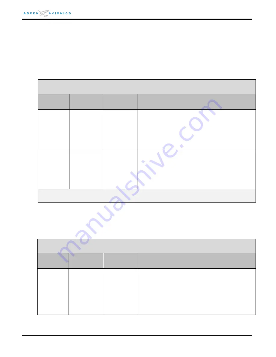
BENDIX KING KI525A EMULATION  

ACU HSI TYPE = 0 

1

DATUM 

SCALING 

2

REFERENCE 

VOLTAGE 

ACU P3-23 

DESCRIPTION 

(with ACU DATUM = NORMAL)


HDG 

ACU P3-22 

500mVdc 

per degree 

up to a 

maximum 

angle of 30⁰, 

or 15Vdc. 

15Vdc 

500mVdc per degree up to a maximum angle of 

30⁰, or 15Vdc. The output remains at +15Vdc from 

31⁰ to 180⁰.  At 181⁰ it switches to -15Vdc. 

Likewise for negative angles (HDG bug left of the 

lubber line) the gradient is -500mVdc per degree 

up to -30⁰. The output remains at -15Vdc from  

-31⁰ to -179⁰. At 180⁰ it switches to +15Vdc. 

CRS 

ACU P3-3 

167mVdc 

per degree 

up to 90⁰, or 

15Vdc. 

15Vdc 

167mVdc per degree up to 90⁰, or +15Vdc. From 

91⁰ to 180⁰ the output diminishes by 167mVdc per 

degree, reaching 0Vdc at 180⁰. For negative angles 

(CRS pointer left of the lubber line) the gradient is  

-167mVdc per degree up to -90⁰. From -90⁰ to  

-179⁰ the output diminishes by 167mVdc per 

degree reaching 0Vdc at 180⁰. 

1

Datum outputs are in reference to ACU P3-11, ACU reference ground. 

2

15Vdc reference may come from ACU P3-9, ACU +15Vdc Out. 

Table 8-5: KI525A Emulation Specifications 


8.2.5.8


NSD-360 Heading and Course Datum Output 

Emulated NSD-360 outputs to drive the heading and course datum inputs of an 

autopilot. 

NSD-360 EMULATION  

ACU HSI TYPE = 1 

1

DATUM


SCALING 

2

REFERENCE 

VOLTAGE 

ACU P3-23 

DESCRIPTION 

(with ACU DATUM = NORMAL)


HDG  

ACU P3-22 

167mVdc per 

degree up to 

90⁰, or 

15Vdc. 

15Vdc 

Reference 

voltage may 

be any 

positive DC 

or AC 

reference 

voltage 

Assuming a reference voltage of 15Vdc, the 

gradient is 167mVdc per degree up to 90⁰, or 

+15Vdc. From 91⁰ to 180⁰ the output diminishes 

by 167mVdc per degree, reaching 0Vdc at 180⁰. 

For negative angles (HDG Bug left of the lubber 

line) the gradient is -167mVdc per degree up to  

-90⁰. From -90⁰ to -179⁰ the output diminishes by 

167mVdc per degree reaching 0Vdc at 180⁰. 

Содержание EFD1000 E5

Страница 1: ...Dual Electronic Flight Instrument EFI Install Manual DOCUMENT 900 00041 001 PAGE 1 226 REVISION D Copyright 2019 Aspen Avionics Inc EFD1000 E5 Dual Electronic Flight Instrument EFI Installation Manual...

Страница 2: ...truments must not be removed See Section 4 The existing turn bank instrument or a backup attitude indicator must be retained for all installations except Aircraft Limited to VFR See Section 4 5 The RS...

Страница 3: ...rs 5578 C Corrected the transmit rate for the ARINC 429 outputs Added a date to the cover Updated paragraph 7 2 11 to add tubing 5588 D Added Figure 4 1A VFR Configuration Added Section 4 5 Special Co...

Страница 4: ...e AML into any 14 CFR Part 23 Class III or IV aircraft or into any part 25 27 or 29 aircraft or non U S registered aircraft requires separate airworthiness approval This document is protected by the C...

Страница 5: ...GULATORY COMPLIANCE 21 1 10 1 TECHNICAL STANDARD ORDER 21 1 10 2 PMA APPROVAL 21 1 10 3 SOFTWARE CERTIFICATION 22 1 10 4 ENVIRONMENTAL COMPLIANCE 22 1 10 5 INSTALLATION APPROVAL 22 1 11 FIELD REPLACEA...

Страница 6: ...R UNIT 2 ACU2 32 3 7 SYSTEM ARCHITECTURE 33 4 STC SPECIFIC REQUIREMENTS AND LIMITATIONS 35 4 1 EFD1000 E5 SYSTEM LIMITATIONS 35 4 2 EA100 INSTALLATION LIMITATIONS EA100 IS OPTIONAL 35 4 3 AUTHORIZED C...

Страница 7: ...R FIGURE 6 2 52 6 8 3 RECESS MOUNTING THE EFD AS PER FIGURE 6 4 54 6 8 3 1 RECESS MOUNT MODIFICATION PROCEDURE 54 6 8 4 EFD BONDING STRAP 59 6 8 5 PITOT AND STATIC CONNECTIONS 59 6 8 6 QUICK CONNECTOR...

Страница 8: ...84 8 ELECTRICAL CONNECTIONS 86 8 1 EFD ELECTRICAL SPECIFICATIONS 86 8 1 1 POWER INPUT 86 8 1 2 RS 232 GPS INPUT 86 8 1 3 RS 232 ADC OUTPUT 86 8 1 4 ARINC 429 GPS INPUTS 86 8 1 5 ARINC 429 VLOC INPUT 8...

Страница 9: ...IRING DIAGRAMS EFD1000 E5 102 9 2 OPTIONAL INTERFACES ACU AND ACU2 103 10 CONFIGURATION AND EQUIPMENT CHECKOUT 134 10 1 WIRING CHECKS 134 10 2 BONDING CHECK 14CFR 23 867 B 134 10 3 INITIAL SYSTEM TURN...

Страница 10: ...NSTALLATION MENU PAGE NETWORK PAGE 148 10 4 6 27 INSTALLATION MENU PAGE DIAGNOSTICS 149 10 4 7 CONFIGURATION DEFINITIONS 149 10 4 7 1 IAS CONFIGURATIONS 149 10 4 7 2 PANEL TILT PITCH ADJ 150 10 4 7 3...

Страница 11: ...11 5 DOCUMENT OPERATIONAL CHECK 172 12 OPERATING INSTRUCTIONS 173 12 1 PILOT CONTROLS 173 12 1 1 OVERVIEW 173 12 1 2 POWER CONTROL 173 13 ENVIRONMENTAL QUALIFICATION FORMS 175 APPENDIX A TROUBLESHOOTI...

Страница 12: ...5 3 Heading Sources 47 Table 5 4 Air Data Sources 47 Table 6 1 Component Weights 50 Table 6 2 Parts Required to Recess Mount each EFD 54 Table 6 3 Static Load Table 57 Table 6 4 RSM Mounting Hardware...

Страница 13: ...Static Quick Connector 59 Figure 6 10 Pitot Static Line Connections 60 Figure 6 11 RSM External Mounting Locations Top Side View all aircraft types 63 Figure 6 12 RSM Internal Mounting Locations Comp...

Страница 14: ...Figure 9 15 Analog NAV Interface 113 Figure 9 15A Narco and Cessna ARC Navigation Radios 114 Figure 9 16 KI525A Emulation Bendix King autopilot to ACU 115 Figure 9 17 S TEC Autopilot to ACU Interface...

Страница 15: ...er of gravity 198 Figure E2 EA100 Block Diagram Bendix King Autopilots 198 Figure E3 EA100 Block Diagram Century Autopilots 198 Figure E4 EA100 Mounting 200 Figure E5 A P AHRS FAIL Annunciator Locatio...

Страница 16: ...EFI Electronic Flight Instrument EHA Evolution Hazard Awareness ESV Evolution Synthetic Vision FAR Federal Aviation Regulations FD Flight Director FPM Flight Path Marker GNAV Combined GPS and VOR radi...

Страница 17: ...EFD1000 E5 Evolution Flight Display PMA 910 00005 004 Configuration Module Assy TSO 910 00003 002 RSM Rev E or later Remote Sensor Module Top Mount TSO 910 00003 003 RSM Rev E or later Remote Sensor M...

Страница 18: ...Connector 1 273 00003 001 Tee Fittings for Pitot Static 0 25 x 0 17 x 0 25 2 271 00001 001 Miniature Hose Clamps 8 412 00004 001 Configuration Module Cable Assembly 1 Table 1 4 903 00001 EFD1000 EFD...

Страница 19: ...h density D Sub connector contacts back shell 1 116 00026 002 DB15 EMI Back shell 1 116 00026 003 DB25 EMI Back shell 1 116 00026 005 DB37 EMI Back shell 1 116 00015 001 Crimp Sockets 77 Table 1 8 903...

Страница 20: ...Breaker Switch 7 5amp optional in lieu of separate C B and switch MS24509 A 7 Tinned Copper Over Braid used in lieu of double shielded wire MIL SPEC AA59569R36T0250 MIL SPEC AA59569R36T0500 RSM Double...

Страница 21: ...le 2112 West Division St Arlington TX 76012 3693 817 461 9473 Info aepetsche com Wirenetics Thermax Cat 5e cable 27737 Avenue Hopkins Valencia CA 91355 661 257 2400 jtoy wirenetics com Positronic Indu...

Страница 22: ...Section 13 1 10 5 Installation Approval Installation of the EFD1000 E5 is FAA approved under AML STC SA10822SC This installation manual contains FAA Approved Data but only when used to install the Asp...

Страница 23: ...Reflective Coated Glass Backlight High Intensity White LED Rotary Knobs Optical Encoder with Momentary Push Dimming Manual Automatic Front Bezel Mounted Sensor 2 1 2 Operational Specifications Operat...

Страница 24: ...1 6 Design Eye Viewing Envelope The following information defines the viewing envelope within which the EFD1000 E5 complies with the equipment standards Minimum and maximum distance from the center of...

Страница 25: ...1 in maximum Measured from Base Length 4 40 in Front to Rear Weight 0 5 lbs 2 2 2 Operational Specifications Operating Temp 55 C to 70 C Storage Temp 55 C to 85 C Max Operating Altitude 55 000 ft Unpr...

Страница 26: ...e CM There is a single hardware part number Configuration Module which is then loaded with the appropriate configuration settings image file that establishes the functionality and feature set of the a...

Страница 27: ...ty 95 at 50 C Input Voltage Provided by EFD Nominal Current Included in EFD Current 2 3 3 I O Specifications Proprietary Digital 2 3 4 Certification Specifications The Configuration Module is certifie...

Страница 28: ...ng Altitude 35 000 ft Cooling None Required Max Humidity 95 at 50 C Input Voltage 11 to 32 VDC Nominal Current 0 5 1 0 Amps 28v 14v 2 4 3 I O Specifications ARINC 429 Inputs 2 Low Speed ARINC 429 Outp...

Страница 29: ...mber 910 00004 101 102 Width 5 75 in including mounting flanges Height 2 25 in Length 4 28 in Weight 1 1 lbs 2 5 2 Operational Specifications Operating Temp 40 C to 55 C Storage Temp 55 C to 85 C Max...

Страница 30: ...BS Interface 1 Output Autopilot Interface 1 Analog port G S and NAV Flag to A P low level 101 Discrete to drive Superflag 102 Heading Synchro 1 Output with 26Vac Reference 2 5 4 Certification Specific...

Страница 31: ...rear portion of the EFD includes a non removable electronics module that contains a full air data computer attitude heading reference system power supplies internal battery and dual processor electron...

Страница 32: ...tion data The Configuration Module connects to the EFD through a short fabricated harness and is fastened to the main wiring bundle of the display Each display has an associated Configuration Module t...

Страница 33: ...system architecture in Figure 3 2 shows the relationships of the EFD1000 E5 with its associated RSM Configuration Module and optional ACU and EA100 Figure 3 1 EFD1000 E5 System Architecture EFD1000 E5...

Страница 34: ...EFD1000 E5 Dual Electronic Flight Instrument EFI Install Manual DOCUMENT 900 00041 001 PAGE 34 226 REVISION D Copyright 2019 Aspen Avionics Inc THIS PAGE IS INTENTIONALLY LEFT BLANK...

Страница 35: ...s not approved for aircraft with a maximum takeoff weight MTOW exceeding 6000lbs This installation is not authorized as a Flight Display for Category II Operations or RVSM Operations 4 2 EA100 Install...

Страница 36: ...eter 1 existing Airspeed indicator 1 existing Turn Bank indicator 1 3 Magnetic Direction Indicator compass Secondary navigation indicator 2 when required see section 4 4 5 IFR GPS navigator input see...

Страница 37: ...4 1A EFD1000 E5 Authorized VFR with Backups Configuration E5 RSM ACU optional CM Required Instruments existing IAS 1 ALT 1 Compass 1 Requires existing Altimeter 1 existing Airspeed indicator 1 Magneti...

Страница 38: ...e indicator may be removed unless it is required for autopilot or flight director purposes It may also be retained and used as the secondary source of attitude if it is desired to remove the turn and...

Страница 39: ...any position in the instrument panel including the co pilot side as the turn and slip or turn coordinator is retained in its original location as part of the backup attitude solution Flight Director d...

Страница 40: ...ion would not require a backup NAV indicator However a GPS with legacy VLOC radio that does not include an integral display with CDI indications approved for navigation will require a backup NAV indic...

Страница 41: ...t placard that permits IFR operation 2 Permanently affix a placard in full view of the pilot stating Operation of This Aircraft is Limited to VFR Only in the same location as the obliterated statement...

Страница 42: ...ield of view see Figure 4 2 NA if no flight director 5 Is a backup navigation indicator required see section 4 4 5 NA if no Backup NAV indicator is required If a backup indicator is required is there...

Страница 43: ...ction 7 1 The EFD1000 E5 system uses an internal battery to permit operation of the EFD1000 E5 during an aircraft charging system failure If the aircraft bus voltage falls below a nominal 12 3V 14V el...

Страница 44: ...Generally unless modified aircraft serial number 16084 and above have standard airspeed indicators and 16083 and below do not The pitot and static systems must still be connected to the EFD1000 E5 be...

Страница 45: ...puts Heading Datum and Course Datum via the ACU the existing HSI DG is no longer required to provide this output to the autopilot When the EFD1000 E5 System is installed the ACU controls all analog na...

Страница 46: ...4xx 5xx GTN 6xx 7xx RS 232 This configuration should not be used Garmin GNS 480 Software v2 0 and below ARINC 429 This configuration should not be used Garmin GNS 480 Software v2 3 ARINC 429 GAMA 429...

Страница 47: ...Air data information is available in the following formats The ACU does not pass thru air data information to its output bus the ACU2 does See Section 8 for ARINC 429 and RS 232 air data output speci...

Страница 48: ...r wiring connections 5 4 7 Flush or Recess Mounting the EFD If there is insufficient clearance between an EFD and the control column when the flight controls are in the full nose down position it will...

Страница 49: ...EFD1000 E5 Dual Electronic Flight Instrument EFI Install Manual DOCUMENT 900 00041 001 PAGE 49 226 REVISION D Copyright 2019 Aspen Avionics Inc THIS PAGE IS INTENTIONALLY LEFT BLANK...

Страница 50: ...the Instructions for Continued Airworthiness It is also required that an accurate description of wire and cable routing be noted on the figures This information will be required later to comply with t...

Страница 51: ...r of a composite or fabric skinned aircraft structure is beyond the scope of this STC To mount the RSM on composite or fabric skin aircraft structures separate FAA approval of the RSM mounting is requ...

Страница 52: ...down on the knobs 6 8 1 EFD Mounting Location The EFD must be mounted approximately centered in the instrument panel per 14CFR 23 1321 d If the two existing instrument holes that contain the attitude...

Страница 53: ...ews NAS1149FN632P washers and MS21044N06 6 32 Nuts It is also acceptable to use existing 6 nutplates 1 Burnish the back of the instrument panel around one of the 6 mounting holes to allow for bracket...

Страница 54: ...ional data to accommodate individual differences in an aircraft can be presented to a Structural DER or Regulatory Authority for approval If the data package is satisfactory the DER or Regulatory Auth...

Страница 55: ...EFD Cutout and Bracket Mounting Hole Locations Using the dimensions from Figure 6 3 as a guide mark the EFD cutout and four bracket mounting holes The clearance notch at the top see detail A is to per...

Страница 56: ...and nuts to 12 in lbs anchoring the brackets to the panel NOTE Spacers A come in a strip of three which can be snapped apart The thickness of the instrument panel will determine how many spacers will...

Страница 57: ...3 13 2B for additional Structural Data Direction of Pull push on bracket Load Factor Static Test Load load factor x EFD weight Forward toward firewall 9 0g 9 0 x 2 9 26 lbs Table 6 3 Static Load Table...

Страница 58: ...ectronic Flight Instrument EFI Install Manual DOCUMENT 900 00041 001 PAGE 58 226 REVISION D Copyright 2019 Aspen Avionics Inc Figure 6 6 Recess Mounting Bracket Dimensions inches Figure 6 7 EFD Mounti...

Страница 59: ...to the EFD1000 E5 via two keyed quick connect fittings These connections will typically require a T fitting to be installed in line with the existing altimeter and airspeed indicators The quick conne...

Страница 60: ...t can be secured away from flight controls Secure each end with the supplied hose clamps 5 Secure pitot and static lines as necessary to prevent interference with other aircraft structures and compone...

Страница 61: ...ainst direct lightning effects 6 9 1 RSM Internal Mounting Typically the RSM will be internally mounted within an area of the aircraft fuselage or wing structure that is magnetically benign For alumin...

Страница 62: ...the tail as measured from the fuselage aft end as shown If it is impossible to find a suitable external mounting location in the preferred area and internal mounting is not possible it may be permissi...

Страница 63: ...Aspen Avionics Inc Figure 6 11 RSM External Mounting Locations Top Side View all aircraft types 12 Preferred Area Hat Rack Baggage Compartment NO ZONE NO ZONE Less Preferred Locations See Note 12 min...

Страница 64: ...6 12 RSM Internal Mounting Locations Composite Fabric Aircraft Hat Rack Baggage Compartment NO ZONE 39 NO ZONE Acceptable Internal Mount Area Composite Fabric 12 12 NO ZONE NO ZONE Acceptable Interna...

Страница 65: ...find a magnetically quiet area free from the effects of magnetic disturbances from flight controls autopilot servos strobes or any other large magnetic field appliance The HMR2300 Smart Digital Magnet...

Страница 66: ...Be sure to check for interference with the following systems operating Servos Alternator Generator and cabling to aircraft battery Blower motors Strobes beacons Pulse equipment DME transponder active...

Страница 67: ...ores Operate flight controls from stop to stop and verify no more than 2 of compass needle movement Should the compass show excessive needle movement it would be required to find a new location or deg...

Страница 68: ...hown in Figure 6 12 The same bonding requirements for an external mounting must be adhered to Though separate approval must be obtained for the RSM structural and in the case of fabric and composite a...

Страница 69: ...o side tilt is 10 degrees in relation to wings level An aluminum shim might be required to keep orientation within limits see Section 6 9 11 for shim fabrication Figure 6 17 RSM Side to Side Max Tilt...

Страница 70: ...own Should the installer wish to deviate from this doubler in size rivet count rivet spacing or doubler thickness they are required to seek separate approval 6 9 8 1 RSM Doubler Fabrication 1 Determin...

Страница 71: ...within 4 see Figure 6 14 Figure 6 20 Masking of Doubler 9 Remove burrs and break sharp edges on the aircraft skin 0 005 0 015 10 Burnish the aircraft skin on the inner surface in the area where the do...

Страница 72: ...rs The supplied Brass hardware should be used NOTE The RSM contains a sensitive magnetometer Nearby ferrous components or hardware can magnetize the RSM and or cause erroneous indications 1 It is not...

Страница 73: ...essary If the RSM exceeds the mounting limits of Section 6 9 7 a shim will be required Fabricate a shim with the dimensions of the RSM baseplate Optionally the shim can be made square and slightly lar...

Страница 74: ...he shim must be bonded to the aircraft skin by removing the paint and prepping the aircraft surface where the shim and RSM will be mounted Remove paint inside the outer footprint of the RSM mounting l...

Страница 75: ...raphs 100 to 114 pages 1 to 8 An unpainted surface of the ACU case must be bonded to aircraft ground either through mounting to a metal shelf or with an installer fabricated bonding strap of wire brai...

Страница 76: ...000 E5 Dual Electronic Flight Instrument EFI Install Manual DOCUMENT 900 00041 001 PAGE 76 226 REVISION D Copyright 2019 Aspen Avionics Inc Figure 6 27 ACU Dimensions inches 15 20 1 1 14 37 19 13 25 1...

Страница 77: ...EFD1000 E5 Dual Electronic Flight Instrument EFI Install Manual DOCUMENT 900 00041 001 PAGE 77 226 REVISION D Copyright 2019 Aspen Avionics Inc Figure 6 28 ACU2 Dimensions inches...

Страница 78: ...EFD wire harness Leave just enough slack in the cable ties so that the configuration module can slide along the EFD cable This will prevent strain on the configuration module connector while the EFD...

Страница 79: ...EFD1000 E5 Dual Electronic Flight Instrument EFI Install Manual DOCUMENT 900 00041 001 PAGE 79 226 REVISION D Copyright 2019 Aspen Avionics Inc THIS PAGE IS INTENTIONALLY LEFT BLANK...

Страница 80: ...ion accessible to the pilot while seated The breaker will be powered from the switched battery or essential bus Label the switch and or breaker ASPEN EFD The switch must be rated for at least 7 5 amps...

Страница 81: ...ielded single conductor wires EFD1000 E5 to RSM wiring does not require the over braid or double shield only what is specified in Section 7 2 6 ACU to GPS ACU to VLOC receiver and ACU to autopilot req...

Страница 82: ...Red Green 3 32 White Orange Brown 4 33 White Yellow Orange White 5 34 White Green Orange 6 35 White Blue Blue Blue White 7 36 White Brown White 7 2 6 2 Assembly using M27500 A24SD7T23 Cable Terminate...

Страница 83: ...screw as shown in Figure 7 3 Figure 7 3 EFD Back Shell Grounds RSM 7 2 7 Configuration Module Wiring The Configuration Module CM connector comes as an assembly with color coded wires within an over b...

Страница 84: ...e is as close to the navigation receiver as practical Do not splice the connection at the back of the NAV indicator 7 2 10 Autopilot Wiring Wire the autopilot to ACU as shown in Section 9 Remove any e...

Страница 85: ...EFD1000 E5 Dual Electronic Flight Instrument EFI Install Manual DOCUMENT 900 00041 001 PAGE 85 226 REVISION D Copyright 2019 Aspen Avionics Inc THIS PAGE IS INTENTIONALLY LEFT BLANK...

Страница 86: ...60 65 configuration 8 1 3 RS 232 ADC Output The EFD1000 E5 Display outputs the following computed air data output signals over the RS 232 bus in Format Z Shadin ADC TYPE 1 and Format C Bendix King ADC...

Страница 87: ...set ILS Energize Label 173 Localizer deviation and validity flags Label 174 Glide Slope deviation and validity flags Label 222 VOR Omni bearing Table 8 3 EFD A429 VLOC Input 8 1 6 ARINC 429 Output Th...

Страница 88: ...5 Table 8 4 EFD1000 E5 A429 GPS Output 8 2 ACU Electrical Specifications 910 00004 all dash numbers 8 2 1 Power Input Nominal Input 14Vdc or 28Vdc Operating Range 11Vdc to 32Vdc 8 2 2 Reserved 8 2 3 V...

Страница 89: ...6Vac in 10 4Vac out DC Offset 0Vdc to 5Vdc Offset applied to Rotor C 8 2 4 2 TO FROM FLAG Input Differential input from a GPS receiver indicating whether flying TO or FROM the active waypoint TO the w...

Страница 90: ...the Lateral LT RT signal from the ACU is valid Valid 0 4 to 0 8Vdc Invalid Less than 0 05Vdc Load Will drive up to three 1000 ohm loads NOTE ACU2 P N 910 00004 102 does not have a low level flag It pr...

Страница 91: ...dc 167mVdc per degree up to 90 or 15Vdc From 91 to 180 the output diminishes by 167mVdc per degree reaching 0Vdc at 180 For negative angles CRS pointer left of the lubber line the gradient is 167mVdc...

Страница 92: ...Reference voltage may be any AC reference voltage Assuming a reference voltage of 26Vac the gradient is 131mVac per degree up to 90 or 11 8Vac From 91 to 180 the output diminishes by 131mVac per degr...

Страница 93: ...c Heading 200 Table 8 8 ACU A429 Output 8 3 ACU2 Electrical Specifications 910 00004 10x only The ACU2 has the same interfaces as the ACU above on connectors J1 J2 J3 plus it adds the following interf...

Страница 94: ...tic heading air data and selected course Can be configured High or Low speed Note Except as shown in the wiring diagrams Section 9 no ARINC 429 interface is approved under the Aspen STC and must be ap...

Страница 95: ...Receiver 5 26 ARINCTX1A OUTPUT ARINC Transmitter 1 27 ARINCTX1B OUTPUT ARINC Transmitter 1 28 Reserved Future Expansion 29 Reserved 30 RS 232TX0 OUTPUT RS 232 TX 31 RS 232RX0 INPUT RS 232 RX0 115kb 3...

Страница 96: ...RSME RSM Connection 6 RSMF RSM Connection 7 RSMG RSM Connection Table 8 11 RSM Pin Out Male Pin Side Solder Cup Side Figure 8 2 RSM Mating Connector Install Side 8 6 Configuration Module Pin Out Pin...

Страница 97: ...UP INPUT GPS Vertical Dev Input J1 14 GPS TO INPUT GPS TO FROM Input J1 15 GPS VERTFLG INPUT GPS Vertical Flag Table 8 13 ACU J1 Pin Out Figure 8 4 ACU J1 Connector as viewed from front of unit Pin Nu...

Страница 98: ...ING VALID OUTPUT Active Low Output when Heading Valid J2 26 DH INPUT N A J2 27 FD VALID INPUT N A J2 28 FD PITCH2 INPUT N A J2 29 ALT ENGAGE OUTPUT N A J2 30 VLOCFLG OUT Common J2 31 GS IN INPUT Glide...

Страница 99: ...7 GPS SELECTED OUTPUT Active Low signal to drive GPS and Autopilot inputs J3 18 OBS SIN OUTPUT Sin of selected course angle H J3 19 OBS COS OUTPUT Cos of selected course angle H J3 20 ROTOR H INPUT OB...

Страница 100: ...external equipment J4 23 429TX3A OUTPUT ARINC 429 Port 3 Transmit A J4 24 429RX3A INPUT ARINC 429 Port 3 Receive A J4 25 400HZ REF HI OUTPUT 400Hz excitation for heading synchro J4 26 HDG X OUTPUT Hea...

Страница 101: ...51 SPARE DISC10 INPUT Discrete Input J4 52 SYN HDG VALID OUTPUT Active Low output when synchro Hdg Valid J4 53 MK12D GS FLG INPUT High impedance Glideslope Flag Narco J4 54 MK12D GS FLG INPUT High im...

Страница 102: ...0A and a PN 101 HSI by providing outputs for HDG Datum and CRS Datum to an autopilot The EFD1000 E5 is compatible with any autopilot that is compatible with a KI 525A NSD 360A or PN 101 HSI Should con...

Страница 103: ...0B 800B 9 19A Cessna 300 400 800 IFCS 9 19B Cessna Navomatic 400 400A 9 19C Cessna Navomatic 300A 9 19D Cessna Navomatic 300 9 20 Bendix FCS 810 9 24 Back Up NAV Indicator internal converter 9 25 Back...

Страница 104: ...D 1 All wires in this manual are 22 AWG unless otherwise noted 2 Connect ground lugs to airframe ground with as short a conductor as possible Connect to airframe ground with as short a conductor as po...

Страница 105: ...Double Shield EFD1000 18 429 VLOC RX2A P2002 24 429 VLOC RX2B 19 23 GARMIN GNC255 1 A429 VLOC NONE I No GPS1 VLOC1 1 Over shield or over braid required on this wire bundle to comply with HIRF Lightnin...

Страница 106: ...48 49 or 50 51 not both GNAV See Figure 9 27 for GNS GTN configuration GNS530 GNS480 and GTN650 750 use same config as GNS430 GPS500 and GTN625 635 725 uses same config as GPS400 4 Over shield or ove...

Страница 107: ...uired on this wire bundle to comply with HIRF Lightning Extend within back shell Ground at both ends 4 Configuration Matrix see Section 10 6 Pins 4 24 may be swapped with pins 5 25 if configured accor...

Страница 108: ...P1001 J101 J1 P3 4 5 16 17 GPS RX1A GPS RX1B 429 TX2A 429 TX2B 16 15 16 33 32 46 10 47 29 48 50 49 51 15 67 48 33 32 4 ID 1 Description D E ID 2 NONE NONE GPS1 No NAV1 GPS1 NAV1 5 3 See Figure 9 15 fo...

Страница 109: ...B 9 14 for GX 50 60 GX 55 65 RS 232 Flight Plan To EFD1000 Pin 9 Analog VLOC 1 Optional Back Up Nav Indicator V L O C 1 See Figure 9 24 9 25 9 26 for Back Up NAV recommendations 2 1 2 3 1 ID 1 Descrip...

Страница 110: ...t DN 12 33 32 P1 31 11 13 8 11 7 14 LAT FLG Vert FLG Vert FLG GPS DN GPS Vert FLG GPS FR GPS Vert FLG N C P2 P1 17 GPS MODE SEL Over shield or over braid required on this wire bundle to comply with HI...

Страница 111: ...to comply with HIRF Lightning Extend within back shell Ground at both ends 1 2 16 Existing OBS LEG switch N C N C N C OBS LEG 3 2 3 4 If existing installation has external OBS LEG switch then splice...

Страница 112: ...13 6 P2 OBS LEG APPR ACTIVE 7 24 31 30 29 10 14 13 12 11 28 29 Vert FLG Vert FLG Vert DN Vert UP 34 15 5 _ _ _ _ _ _ P1 GX 55 GX 50 GX 60 GX 65 OBS HOLD ACTIVE 2 3 The GX 50 60 share pin 29 between Ve...

Страница 113: ...lope interface is for units with GS option 3 P2 P2 KX170A 170B 175B P171 3 4 See manufacturers documentation for KN 70 73 75 Glideslope connections 3 _ _ _ _ _ 4 2 2 See Figure 9 27 for SL 30 configur...

Страница 114: ...placement radios Composite Phase VOR1 2 180 Note The composite output from these radios use a DC offset voltage A capacitor is required as shown below Note The Glide Slope output from some Narco radio...

Страница 115: ...P3 17 ACU HSI TYPE 0 KFC 275 KCP220 P2201 KCP220 P2202 32 16 33 17 2 3 11 28 27 10 22 _ 38 _ _ _ _ _ _ _ _ _ _ _ _ _ _ _ _ _ KFC 250 275 HDG CRS Datum for 3 Instruments KCS 55A only 1 Configuration Ma...

Страница 116: ...nnection between GPS and 55X When using the EFD1000 GPSS only this pin is left open 2 3 4 3 ACU Refer to autopilot manufacturers documentation for autopilot side integration information including auto...

Страница 117: ...UM CRS HDG COM HDG CRS EXT Century Heading System Adapter CD175 2 17 20 ACU When replacing a DC version NSD 360 If the existing DG HSI is to remain in the aircraft do not parallel HDG CRS Datum with A...

Страница 118: ...nufacturers documentation for autopilot side integration information including autopilot STC compliance data and for autopilot and flight director checkout procedures This drawing as it pertains to th...

Страница 119: ...PARTS T1 Use Triad SP 66 MIL No TF5S21ZZ T2 T3 New Installations Use Triad SP 67 MIL No TF5S21ZZTY T2 T3 Existing Installations May continue to use a SP 66 unless performance was unacceptable then us...

Страница 120: ...ter Configuration Matrix see Section 10 Refer to autopilot manufacturers documentation for autopilot side integration information including autopilot STC compliance data and for autopilot and flight d...

Страница 121: ...o these units provided NAV1 and NAV2 inputs are jumpered together 300B 400B 800B CA 550A FD 3 4 Refer to autopilot manufacturers documentation for autopilot side integration information including auto...

Страница 122: ...autopilot no matter the position of the Nav1 2 selector switch Z N P _ _ 5 Y S ILS ENERGIZE Cessna 300 400 800 IFCS Mode Controller S530A 3 4 Refer to autopilot manufacturers documentation for autopi...

Страница 123: ...n line Verify 10Vac goes to ACU P3 23 and 4 5Vdc goes to ACU P3 25 before connecting the ACU Sometimes the 10Vac and 4 5Vdc signals are reversed at the mode controller 1 EXT OFFSET P3 CA 520 B AP Mode...

Страница 124: ...5 Vdc 0 4 5Vdc 90 8 5Vdc Refer to autopilot manufacturers documentation for autopilot side integration information including autopilot STC compliance data and for autopilot and flight director checko...

Страница 125: ...ence Autopilot can only be connected to ACU 1 in a dual ACU configuration 1 2 Refer to autopilot manufacturers documentation for autopilot side integration information including autopilot STC complian...

Страница 126: ...lot STC compliance data and for autopilot and flight director checkout procedures This drawing as it pertains to the non Aspen equipment is for reference only D t HDG LO CRS LO B A F E P2 18 37 16 35...

Страница 127: ...lding as required Splice connections as close to NAV receiver as possible Do not splice from back of NAV indicator GS lines will only be connected on NAV units with this option Some Nav Receivers have...

Страница 128: ...up is shown on Figure 9 15 2 3 4 NAV Indicator NAV FLG NAV FLG CDI RIGHT CDI LEFT TO FROM OBS RES A H OBS RES C OBS RES G OBS RES F OBS RES E OBS RES D 3 2 Parallel all lines shown maintaining shield...

Страница 129: ...Figures 9 6 and 9 7 for EFD1000 to GNAV interface Refer to manufacturers documentation to verify the integration data and for information regarding checkout procedures This drawing as it pertains to t...

Страница 130: ...NT ARINC 429 SETUP CH_IN SEL SPEED SDI 2 EFIS LOW See Note 1 CH_OUT SEL SPEED SDI 1 GAMA 429 GFX Int LOW 2 See Note 1 2 VOR ILS LOW 2 SYS1 or SYS2 GAMA 429 GFX Int this configuration has Flight Plan i...

Страница 131: ...ADC TYPE 1 Format Z Garmin ADC TYPE 2 Format C King If ACU is installed parallel this EFD output with ACU and other device requiring A429 Heading and or Air Data 2 4 A429 TX2A A429 TX2B 5 P3 to optio...

Страница 132: ...synchro heading input must use the same 400HZ reference Either wire the 400HZ from the external source in to both the ACU2 and the device or use ACU2 400HZ output as reference to device Note if a ext...

Страница 133: ...EFD1000 E5 Dual Electronic Flight Instrument EFI Install Manual DOCUMENT 900 00041 001 PAGE 133 226 REVISION D Copyright 2019 Aspen Avionics Inc THIS PAGE IS INTENTIONALLY LEFT BLANK...

Страница 134: ...red wiring bundles 3 Apply aircraft power and close the EFD and ACU circuit breakers and the EFD master switch if installed 4 Verify proper voltage on EFD main connector pins 1 2 and 3 and that there...

Страница 135: ...ious menu page Editable menu items are displayed in white text on a blue background non editable menus items are green text on a blue background while grey text on a blue background is disabled from e...

Страница 136: ...at the beginning of the section and record the configuration in each table as shown below Make a copy of the appropriate section with the information recorded for inclusion into the Instructions for C...

Страница 137: ...v1 0 Feature Options Actual Setting ACU HSI TYPE 0 1 0 KI525A 1 NSD360 ACU FD TYPE 0 1 3 4 0 NONE 1 KI256 3 G550 ACU DATUM NORMAL REVERSED FD PITCH OFFSET ADJ 10 0 to 10 0 degrees FD ROLL OFFSET ADJ 1...

Страница 138: ...H or other legal form of documentation e g Placard 10 4 6 1 Installation Menu Page IAS CONFIG A All standard airspeed indicators that use a Vne will set the MOL TYPE to 1 and then enter the Vne in the...

Страница 139: ...is 226 KIAS to 15 500 feet and then Vmo decreases 4 KIAS per 1 000 feet Known values Vmo 226 ALT1 15500 KNOTS 4 ALT2 1000 MAX ALT A C service ceiling Use MOL PARAM SEL to select Vmo ALT1 KNOTS ALT2 Us...

Страница 140: ...Notes 10 4 6 4 Installation Menu Page IAS CONFIG D NOTE These selections are rotorcraft only and are grayed out Does not apply to EFD1000 E5 10 4 6 5 Installation Menu Page IAS CONFIG E This menu is u...

Страница 141: ...N VSPD EDIT UNLOCKED LOCKED Not Used Not Used Notes 10 4 6 7 Installation Menu Page IAS CONFIG G IAS DISPLAY DISABLE will remove the airspeed bug from the tape the upper left window and the left knob...

Страница 142: ...have a Configuration Matrix table that will be used to set ID 1 and ID 2 INSTALLATION MENU PAGE NAV SETUP A Feature Options Actual Setting GPS NAV 1 NONE A B C D E G H I M GPS NAV 2 NONE Not Used Not...

Страница 143: ...EFD because if it was running low speed when powered up it will continue to run low speed even if changed to high above until it boots back up 10 4 6 11 Installation Menu Page RS 232 CONFIG A The fol...

Страница 144: ...1 NONE ADC TYPE 1 ADC TYPE 2 232 OUT PORT 2 NONE ADC TYPE 1 ADC TYPE 2 232 OUT PORT 3 NONE ADC TYPE 1 ADC TYPE 2 Notes ADC TYPE 1 Z Shadin format ADC TYPE 2 C Bendix King C format 10 4 6 13 Installat...

Страница 145: ...01 and 002 RSM BOTTOM 003 RSM INSTALLATION MENU PAGE MISC CONFIG A Feature Options Actual Setting RSM Orientation TOP BOTTOM Inverted orientation RSM GPS Enable Not applicable RSM GPS USAGE Not applic...

Страница 146: ...e Options Actual Setting COMPOSITE PHASE VOR1 2 0 0 180 0 GPSS GAIN 0 5 to 2 0 0 1 increments CRS SDI COMMON NAV 1 2 OBS DISPLAY Not applicable Pitch Sync for Helicopters Not applicable 10 4 6 19 Inst...

Страница 147: ...ble 6 to 6 HDG SEL 060 KEY 4 HDG ADJ KEY 5 Editable 6 to 6 HDG SEL 090 KEY 4 HDG ADJ KEY 5 Editable 6 to 6 HDG SEL 120 KEY 4 HDG ADJ KEY 5 Editable 6 to 6 HDG SEL 150 KEY 4 HDG ADJ KEY 5 Editable 6 to...

Страница 148: ...Menu Page AOA CONFIG This page not applicable to the EFD1000 E5 10 4 6 26 Installation Menu Page NETWORK PAGE This menu is for diagnostic purposes only unless an EA100 is installed For EA100 installat...

Страница 149: ...ENU button All data will be saved as it was displayed on each page The system will reboot and INITIALIZING will appear on the display for approximately 40 seconds Normal operation continues 10 4 7 Con...

Страница 150: ...configured to look exactly like the mechanical indicator Tapes are turned off and cannot be turned on by pilot LOCK ON Tapes are always enabled and cannot be turned off by pilot NOTE Tapes cannot be l...

Страница 151: ...he angle could shift when the technician boards the aircraft This measurement will be entered in the EFD1000 as CORRECTED PITCH ATTITUDE Nose high is degrees Figure 10 4 Illustration of aircraft 2 nos...

Страница 152: ...FD1000 should the aircraft fly consistently slightly nose high or nose low in cruise trim It is not necessary to perform the RSM Calibration after making changes to this setting 10 4 8 NAV Setup Confi...

Страница 153: ...nance activities that could affect RSM accuracy Such activities might include but are not limited to the replacement of the RSM replacement of the Configuration Module installation of a mechanical or...

Страница 154: ...is Rejected and the calibration procedure is re run After the calibration is accepted headings are checked using a calibrated reference i e a sight compass every 30 starting from North to verify that...

Страница 155: ...ed to the Vertical Component on the EFD1000 E5 Diagnostic Page in the installation menu Obtaining Vertical Component Z from EFD1000 E5 Enter the EFD1000 E5 installation menu and navigate to the last m...

Страница 156: ...Z Z2 to the NOAA value When level the RSM Z value should be within 0 03 of the NOAA value 10 5 1 2 Conventional Gear RSM Calibration Procedure Perform the RSM calibration procedure per Section 10 5 2...

Страница 157: ...2 B CR R Imaginary pivot point R Radius to pivot point approximately equal to wingspan 30ft 1 Starting Point A Established Constant Rate turn 10 seconds after 1 CR Constant Rate Turn must continue unt...

Страница 158: ...ding to the nearest 0 1 degrees will be continuously displayed adjacent to the CAL HDG menu field NOTE Verify CAL HDG is within 25 degrees of a calibrated compass source prior to starting the RSM Cali...

Страница 159: ...meter Calibration Complete message occurs between B D of Figure 10 10 then REJECT the results and re run the procedure Figure 10 13 Aircraft Turning At the end of the calibration routine the ACCEPT CA...

Страница 160: ...for 5 seconds and return the RSM CALIBRATION menu page to its initial state Figure 10 15 Results Accepted Pressing the REJECT CALIBRATION selection shall reject the calibration results Reject the resu...

Страница 161: ...on Installation Final Check Sheet of Appendix B and verify heading viewed on compass card is within 4 degrees using a calibrated heading source i e sight compass compass rose Record the actual EFD he...

Страница 162: ...UTION Do not exceed the aircraft s maximum Airspeed Altitude or Vertical Speed at anytime during the testing Damage could result to the pre existing aircraft instruments NOTE When changing indicated a...

Страница 163: ...ully functional interface 10 6 5 1 All GPS interfaces 1 Allow the GPS1 receiver to acquire a valid position and enter a Direct To waypoint or a Flight Plan 2 Verify GPS groundspeed is displayed on the...

Страница 164: ...lling the EFD and ACU circuit breakers 10 6 8 Autopilot Sensor Test Refer to autopilot manufacturer s post installation check out procedures for complete autopilot post installation ground checks At a...

Страница 165: ...Verify that the external power voltage the power to the EFD is at the appropriate level for the aircraft and the last line on the Menu page shows BATT CHARGING 3 With the EFD Menu displayed press the...

Страница 166: ...nt for 20 seconds each 4 Operate all aircraft lighting including position lights strobe lights navigation lights and all other forms of lighting for 20 seconds each 5 Operate all environmental equipme...

Страница 167: ...MARKER BEACON Verify the operation of each Marker Beacon Receiver while monitoring the effects of the Threat equipment No 1 No 2 ADF If Installed Verify the operation of each ADF receiver while monito...

Страница 168: ...eral Threat equipment SAFETY EQUPIMENT WEATHER RADAR If Installed Verify the function of the weather radar system while monitoring the effects of the Threat equipment Prior to ground operation of the...

Страница 169: ...rference while monitoring the effects of the Threat equipment 10 6 14 Flight Control Interference Check CAUTION Verify control surfaces are free and clear With the EFD mounted in the instrument panel...

Страница 170: ...lectronic Flight Instrument EFI Install Manual DOCUMENT 900 00041 001 PAGE 170 226 REVISION D Copyright 2019 Aspen Avionics Inc 10 6 16 EA100 Adapter Testing See Appendix E for EA100 Adapter configura...

Страница 171: ...ect with reference to the horizon 11 2 Heading Card Flight Checks a Make a 180 degree coordinated turn to the right and verify that the compass scale and numerical heading indication correctly track t...

Страница 172: ...and verify the aircraft tracks to the VOR d Enter a valid flight plan or Direct To on the GPS Couple the GPS to the E5 Engage the autopilot in NAV Mode verify the autopilot tracks the GPS Note GPSS is...

Страница 173: ...y that allows the system to continue to operate in the event of a failure of the aircraft electrical system The typical EFD1000 E5 installation receives aircraft power from the battery bus via a dedic...

Страница 174: ...019 Aspen Avionics Inc In the unlikely event that the normal power control is not working the EFD may be forced to shut down by first pulling its associated circuit breaker and then pressing and holdi...

Страница 175: ...st performed Fungus 13 0 Equipment identified as Category X no test performed Salt Fog Test 14 0 Equipment identified as Category X no test performed Magnetic Effect 15 0 Equipment tested to Category...

Страница 176: ...15 0 Equipment tested to Category Z causes 0 5 deg deflection to compass 0 3 meter away Power Input 16 0 n a Powered from EFD display Voltage Spike 17 0 n a Powered from EFD display Audio Freq Conduc...

Страница 177: ...ent identified as Category X no test performed Fluids Susceptibility 11 0 Equipment identified as Category X no test performed Sand and Dust 12 0 Equipment identified as Category X no test performed F...

Страница 178: ...EFD1000 E5 Dual Electronic Flight Instrument EFI Install Manual DOCUMENT 900 00041 001 PAGE 178 226 REVISION D Copyright 2019 Aspen Avionics Inc THIS PAGE IS INTENTIONALLY LEFT BLANK...

Страница 179: ...EFD1000 E5 Dual Electronic Flight Instrument EFI Install Manual DOCUMENT 900 00041 001 PAGE 179 226 REVISION D Copyright 2019 Aspen Avionics Inc Appendix A Troubleshooting...

Страница 180: ...wired RSM a Fail x a Check RSM to EFD wiring for shorts or opens Repair or replace RSM Repair or replace EFD IMU a Fail a Replace EFD ADC a Fail a Replace EFD ADAHRS a Fail a Replace EFD b Initializin...

Страница 181: ...EV button for 20 seconds or unplug EFD internal battery for 3 seconds d EFD is defective d Repair or replace EFD Display flashes on off black white or blue white repetitively a Configuration Module un...

Страница 182: ...t have a valid TO waypoint and position b Allow GPS to acquire a position and enter a flight plan or Direct To c GPS or VLOC receiver failed c See GPS VLOC manufacturer s instructions for troubleshoot...

Страница 183: ...ation away from buildings and other ferrous objects d Ferrous hardware used to mount RSM d Only non ferrous screws nuts washers may be used on RSM e Airframe or external magnetic interference e Check...

Страница 184: ...low the autopilot manufacturer s guidelines for adjusting roll null centering No VDI or glide slope display on EFD a CRS pointer more than 100 from lubberline b ILS frequency not selected a Rotate CRS...

Страница 185: ...EFD1000 E5 Dual Electronic Flight Instrument EFI Install Manual DOCUMENT 900 00041 001 PAGE 185 226 REVISION D Copyright 2019 Aspen Avionics Inc Appendix B Installation Final Check Sheet...

Страница 186: ...EFD Heading Calibrated Heading Source Tolerance Actual EFD Heading 30 4 210 4 60 4 240 4 90 4 270 4 120 4 300 4 150 4 330 4 180 4 360 4 Complete by performing test of Section 10 6 1 IAS Setting Band...

Страница 187: ...ilot Sensor Test if installed 10 6 9 10 6 10 Ancillary Equipment Heading and Air Data if connected List equipment interfaced 10 6 11 Battery Capacity Check Internal battery 80 Charge 10 6 12 TAPES Con...

Страница 188: ...ring cabling from the backup turn and bank altimeter or airspeed indicator is routed directly behind the fan on rear of the EFD1000 E5 display 6 9 4 RSM location are 2 degrees of needle deflection on...

Страница 189: ...ata package is to be given to owner operator for inclusion in aircraft permanent records EA100 Adapter Installations Only Appendix E A P AHRS FAIL annunciator installed in the pilot primary field of v...

Страница 190: ...ual Electronic Flight Instrument EFI Install Manual DOCUMENT 900 00041 001 PAGE 190 226 REVISION D Copyright 2019 Aspen Avionics Inc Appendix C Sample of AFMS Section 1 2 Installed Equipment Configura...

Страница 191: ...ting the installed equipment and backup equipment type Sample Installed Equipment Configuration Matrix The following sample installation is an EFD1000 E5 with a GNS 430W and an EA100 It is using the T...

Страница 192: ...EFD1000 E5 Dual Electronic Flight Instrument EFI Install Manual DOCUMENT 900 00041 001 PAGE 192 226 REVISION D Copyright 2019 Aspen Avionics Inc THIS PAGE IS INTENTIONALLY LEFT BLANK...

Страница 193: ...EFD1000 E5 Dual Electronic Flight Instrument EFI Install Manual DOCUMENT 900 00041 001 PAGE 193 226 REVISION D Copyright 2019 Aspen Avionics Inc Appendix D Component Maintenance Manual CMM...

Страница 194: ...that which is described Aspen Avionics document 900 00012 001 Instructions for Continued Airworthiness Service Life None Specified Field Replaceable Parts Description Aspen Part Number EFD Internal Ba...

Страница 195: ...right 2019 Aspen Avionics Inc Appendix E EA100 Adapter Optional Autopilot Attitude Adapter Replaces the Bendix King KG258 KI254 KI255 KI256 to the KAP100 150 and KFC150 200 250 autopilots And Replaces...

Страница 196: ...s approved by this STC when an EA100 is installed KI 255 KI256 and Century AI FD indicators must not be removed as the EFD1000 E5 cannot display FD commands Therefore these indicators must be relocate...

Страница 197: ...equired Max Humidity 95 at 50 C Input Voltage 14 and 28 VDC Nominal Current 0 25 0 5 Amps 28v 14v I O Specifications Ethernet Port 1 Digital Autopilot Pitch gyro Out 1 Analog Autopilot Roll gyro Out 1...

Страница 198: ...t Flight Computer Ethernet Pitch Hi Roll Hi Ref Voltage 2A 14 28v A P AHRS Fail Lamp A P C B A P Disconnect Switch Existing Relay COMM Relay Energized Relay Relaxed A P Disconnect A P AHRS A P INTRLK...

Страница 199: ...on It is recommended to mount the EA100 as close to the autopilot computer as possible The EA100 has no user interface and therefore can be remote mounted in any orientation as long as it is accessibl...

Страница 200: ...STC and will require separate FAA approved data Structural DER analysis or static testing should be accomplished to the following ultimate load factors for items of mass within the cabin or cockpit u...

Страница 201: ...w A two ampere trip free resettable push pull type circuit breaker must be installed for the EA100 in a location accessible to the pilot while seated The power source for the EA100 is the same as that...

Страница 202: ...bels in the panel and be readable and discernible lit at night Primary Field of View for the purpose of this STC uses the location of the EFD as the measuring point The A P AHRS FAIL light must be wit...

Страница 203: ...onnector DB 15 is suggested with the wires connected per Figure E7 or E7A below c Select the appropriate TR Junction box i TR1 Century 21 31 41 2000 4000 the three 3 transformers are Triad SP 66 MIL T...

Страница 204: ...21 31 41 2000 4000 Figure E7A TR2 Century IIB III IV E5 6 Electrical Connection EA100 P1 Connector PIN NAME INPUT OUTPUT FUNCTION 1 ETHERNET TX OUTPUT ETHERNET TX OUT TO EFD1000 2 ETHERNET TX OUTPUT...

Страница 205: ...4 38 RESERVED 39 A P INTRLK COMM INPUT COMM CONTACT ON RELAY 40 A P INTRLK RELAXED OUTPUT RELAXED STATE OF RELAY 41 A P INTRLK ENERGIZED OUTPUT ENERGIZED STATE OF RELAY 42 A P AHRS VALID OUTPUT ENERGI...

Страница 206: ...EFD1000 39 ENET TX ENET RX 2A 8 15 7 14 P N 412 00013 00x 37 1 EA100 to EFD1000 Ethernet connection must use Aspen P N 412 00013 00x cable Shields must be terminated within the EA100 and EFD back shel...

Страница 207: ...NO NC A P DISC Existing AP DISC Relay A P DISC IN 19X1 19X2 B EA100 41 39 18 3 16 1 P2 AP EXCITE HI AP EXCITE LO AP ROLL HI AP ROLL LO A P INTRLK COMM A P INTRLK ENERGIZED 17 2 AP PITCH HI AP PITCH LO...

Страница 208: ...sures the autopilot cannot be engaged or will disengage if the EA100 attitude is invalid The autopilot sonalert or disconnect tone must not be interrupted with this relay Wire as shown 20 AWG wire may...

Страница 209: ...circuit must be run through an internal relay within the EA100 This ensures the autopilot cannot be engaged or will disengage if the EA100 attitude is invalid The autopilot sonalert or disconnect tone...

Страница 210: ...t be engaged or will disengage if the EA100 attitude is invalid Wire as shown P2992 After w 10 GYRO REF KCP299 Flight Computer with KA141 with P N 065 5016 XX Adapter Board for 3 instruments Only KCP2...

Страница 211: ...KCP299 flight computers with adapter board 065 5016 XX may use this drawing Flight computers with 065 5015 XX adapter boards not approved 18 AWG wire may be spliced to a 22 AWG wire of no more than 4...

Страница 212: ...om Computer AMP pin N or relay and install new pin wire or cut wire and splice on new wire Run new wire from AMP pin N or relay to EA100 P2 41 3 Before A P Disc and Relay partial equals Existing Wires...

Страница 213: ...shown CD18 Remove wire from CD76 B Relay Box and install new pin wire or cut wire and splice on new wire Run new wire from CD76 B to EA100 P2 41 3 Before Trim Enable Ap Disc and Century Relay Box par...

Страница 214: ...s shown CD64 Remove wire from CD81 B 1A544 Relay Box and install new pin wire or cut wire and splice on new wire Run new wire from CD81 B to EA100 P2 41 3 After TR2 Transformer Interface box must be f...

Страница 215: ...e from CD186 4 and install new pin wire or cut wire and splice on new wire Run new wire from CD186 4 to EA100 P2 41 3 Before A P DISC Switch OR No previous switch Existing Wire A P DISC After A P DISC...

Страница 216: ...isconnect tone must not be interrupted with this relay Wire as shown CD176 Remove wire from CD200 19 and install new pin wire or cut wire and splice on new wire Run new wire from CD200 19 to EA100 P2...

Страница 217: ...cannot be engaged or will disengage if the EA100 attitude is invalid The autopilot sonalert or disconnect tone must not be interrupted with this relay Wire as shown CD176 CD144 Remove wire from CD184...

Страница 218: ...the autopilot cannot be engaged or will disengage if the EA100 attitude is invalid The autopilot sonalert or disconnect tone must not be interrupted with this relay Wire as shown CD176 Remove wire fro...

Страница 219: ...autopilot cannot be engaged or will disengage if the EA100 attitude is invalid The autopilot sonalert or disconnect tone must not be interrupted with this relay Wire as shown CD176 Remove wire from C...

Страница 220: ...r the resistor divider network Century A P excitation is 28Vp p before network Use 2 90 as the setting for all Century IIB III and IV autopilots regardless of what is measured Voltage is noted for tro...

Страница 221: ...reaker Power up the autopilot a Verify the AP AHRS FAIL light extinguishes b Press Menu on the EFD and then press the AHRS RESET button twice on the EFD Verify the AP AHRS FAIL light turns on and then...

Страница 222: ...9 Autopilot Gyro Alignment See Tech Note 2010 10 for instructions on using the EA100 Alignment Tool and the autopilot manufacturer s alignment procedure to make these adjustments Bendix King Autopilo...

Страница 223: ...aft does not lose more than 100ft during the turn Verify the autopilot rolls out on the HDG bug with little overshoot e Turn the HDG Bug 90 degrees right During the turn record the maximum bank angle...

Страница 224: ...Using the Pitch Modifier pitch rocker switch press the up side of the switch to initiate a climb attitude of about 5 degrees Verify the aircraft climbs and maintains a consistent 5 degree 2 degree att...

Страница 225: ...ft Bank Angle HDG ALT Maximum Right Bank Angle ATT ALT Maximum Left Bank Angle with Roll Knob if applicable ATT ALT Maximum Right Bank Angle with Roll Knob if applicable HDG ALT ALT HOLD mode does it...

Страница 226: ...formed Salt Fog Test 14 0 Equipment identified as Category X no test performed Magnetic Effect 15 0 Equipment is Category Z Power Input 16 0 Equipment tested to Category B Voltage Spike 17 0 Equipment...

Отзывы: