background image


Page


21


of


38


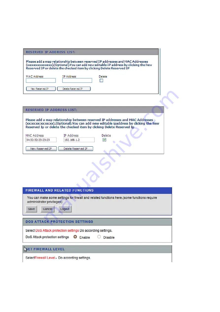
1. Under Reserved IP Address List, click New Reserved IP

2. Fill in the MAC address and IP address. 

3. Click Save to commit the changes. 


To delete a reserved IP: 

1.


Under Reserved IP Address List, click Delete Reserved IP:. 


2. Check the Delete box next to the address to delete. 
3. Click Delete Reserved IP button. 

3.2.2 Firewall (Router Build Only) 
Choose the SECURITY tab to open the LAN Settings, then click FIREWALL on the 
LAN 

Settings screen: 


To set the basic firewall settings: 
1. Under Set Firewall Level, select Enable or Disable to enable or disable the 

Содержание PL9571-WAP

Страница 1: ...PlugLink 500 Wireless N Adapter User s Guide PL9571 WAP 66 0377 01Rev 001 ...

Страница 2: ...user s guide may not be currently available Refer to the most recent product announcement for information about feature and product availability This user s guide contains the most current information available at the time of publication When new and or revised information becomes available this entire user s guide is updated and distributed to all registered users Asoka PlugLink and the Asoka log...

Страница 3: ...evices In that event your right to use the equipment may be limited by FCC regulations and you may be required to correct any interference or radio or television communications at your own expense You can determine whether your equipment is causing interference by turning it off If the interference stops it was probably caused by the Asoka equipment or one of its peripheral devices If the equipmen...

Страница 4: ...d services We encourage you to visit us at http www asokatech com Customer Service Available from Monday through Friday from 9 00 am to 5 00 pm Pacific Time by calling 408 550 8167 or through email at custserv asokatech com Technical Support Technical support is available Monday through Friday from 8 00 am to 5 00 pm Pacific Time by calling 408 550 8173 or through email at support asokatech com Pl...

Страница 5: ...out PL9571 5 Chapter 4 8 Preparing to Install 8 Chapter 5 9 Installing PL9571 9 Chapter 6 11 Logging on 11 Chapter 7 13 Basic Configuration 13 Chapter 8 20 Advanced Configuration 20 Chapter 9 33 Technical Support 33 Chapter 10 34 Technical Specification 34 Chapter 11 33 FCC Statement 35 Chapter 12 34 Warranty Information 36 ...

Страница 6: ...ew cabling This unit will not interfere with other household appliances such as hair dryers vacuum cleaners or microwave ovens Consuming only 7 watts of power it is environmentally friendly and will not noticeably increase your electrical bill It is a simple secure and reliable choice for web surfing playing games and complimenting your existing wireless network mp3 streaming and even video sharin...

Страница 7: ...duct Do not open the cover or casing on this product and or alter this product in any way Follow common household electrical safety practices If you have any questions or concerns regarding these safety measures please contact Technical Support via email at support asokatech com or via phone at 408 550 8173 Monday through Friday between 9 00 am and 5 00 pm PST excluding holidays ...

Страница 8: ...below Figure 3 1 PL9571 WAP Front Panel You can use the status lights to verify connections Viewed from top to bottom left to right the table describes the lights on the front panel of the unit Table 3 1 Status Light Descriptions Power On Indicates Device Powered On Off Indicates No Power PLC Activity Blinking The colors act as throughput indicators Indicates Activity on Powerline Green means good...

Страница 9: ...C MAC Address Device MAC Address Serial number Note For future convenience please write this information down in your Warranty and Support Information Card Figure 3 3 Rear Label Buttons The PlugLink 500 Wireless N Adapter device has three push buttons SW1 Left Button Powerline Security The NID button allows you to set a randomized Network Encryption Key NEK by pressing it You can then have additio...

Страница 10: ...wireless security by simply pushing a button This requires software and a network adapter that supports this feature 2 This button allows you to configure wireless power SW3 Resets the PlugLinK9571 back to factory default settings Press and hold the button with a pin or sharp object for about 2 seconds until you see the lights on the device flash briefly ...

Страница 11: ... outlets It can also easily compliment your existing network by connecting to any device with a 10 100BaseT Ethernet capable device To setup a PLC PowerLine Communication Network you will need One 1 PL9571 WAP device One 1 PL9660 Q1 device sold separately Standard Cable DSL gateway provided by your ISP Figure 4 1 Connecting PL9571 WAP with PL9661 ETH diagram ...

Страница 12: ...g property or degrade the network performance Plug the PlugLink 500 Wireless N Adapter into the wall outlet vertically right side up 1 Use the Ethernet cable shipped with your PlugLink HD AV Adapter PL9660 Q1 PL9660 Q1 not included sold separately to a LAN port on your router 2 Plug the PlugLink HD AV Adapter PL9660 PL9660 Q1 not included into a nearby wall outlet Figure 5 1 Connecting the PL9661 ...

Страница 13: ...gLink 500 Wireless N Adapter is Asoka You will be prompted for your Encryption Key The default Encryption Key is the last 10 digits of the serial number The serial number is printed on the PL9571 label If you changed the default network name SSID be sure to use the correct network name SSID you set in the PlugLink 500 Wireless N Adapter Wireless security is enabled by default on the PL9571 WAP For...

Страница 14: ...ddress field Press Enter to open the login screen Figure 6 1 Login Address For security the PL9571 WAP has its own user ID and password When prompted enter admin for the user ID welcome for the password both in lower case letters and press Login To change the login password see Setting or Changing the Administrative Login Information on chapter 10 Figure 6 2 Login Screen ...

Страница 15: ...n screen opens use the default user name admin and password welcome Click Login Note that user accounts are managed in User Account Management and can be changed after the first login The web interface opens to the basic devices information ...

Страница 16: ... A confirmation screen appears The router will now work in AP mode To configure router mode using the AP Unselect the check box Enable Access Point Mode Router Build Software that is built with BUILD_CONFIG router in the build process user scan select between full router mode and AP mode AP Build Software not built using BUILD_CONFIG router For AP build Enable AP Mode is selected automatically and...

Страница 17: ...nt Mode To add a PPPoE internet connection See To set the router IP address on page 24 for how to configure the router to the Internet connection Much of this information is obtained from the ISP 1 Choose the NETWORK tab to open the Network Connection Settings 2 At Name of Connection make sure Choose New Connection is selected 3 Select the connection type PPPoE ...

Страница 18: ...the Network Connection Settings 2 At Name of Connection make sure Choose New Connection is selected 3 Select the connection type Static 4 Fill in the boxes for IP Address Subnet mask code Default gateway Preferred DNS Alternative DNS optional 5 Click Save to commit the changes To delete an internet connection 1 Choose the NETWORK tab to open the Network Connection Settings 2 At Name of Connection ...

Страница 19: ... protected setup WPS WPS allows easy setup of client devices that support WPS Choose the NETWORK tab then choose the WLAN SETTINGS tab to open the Radio Settings screen Note that WPS configures one client device at a time Repeat the instructions for each client device that supports WPS ...

Страница 20: ...k the WPS button on the client device then click the WPS button on the router board After the client device has been configured click OK See the client device documentation for more instructions For a client device that asks for a Router PIN number enter the PIN number listed on the web page or on the label on the bottom of the router After the client device has been configured click OK See the cl...

Страница 21: ...ttings section of WLAN settings 2 Select the mode channel and transmission power levels 3 Click Save to commit the changes In radio settings click Show Advanced Setting to show more radio settings View the basic wireless settings on the wireless settings screen Click Show Advanced Setting to show more wireless settings ...

Страница 22: ...Page 19 of 38 View the wireless security mode settings on the WLAN settings screen ...

Страница 23: ... Choose the NETWORK tab to open the Network Connection Settings LAN SETTINGS to open the LAN Settings screen To set the router IP address 1 Under LAN settings enter the router IP address and subnet mask 2 Click Save to commit the changes To set the IP address reserve router build only ...

Страница 24: ... Reserved IP Address List click Delete Reserved IP 2 Check the Delete box next to the address to delete 3 Click Delete Reserved IP button 3 2 2 Firewall Router Build Only Choose the SECURITY tab to open the LAN Settings then click FIREWALL on the LAN Settings screen To set the basic firewall settings 1 Under Set Firewall Level select Enable or Disable to enable or disable the ...

Страница 25: ...e the DOS attack protection feature 2 Click Save to commit the changes To add a MAC filter set 1 In the MAC Address Filter Rules Under Router Mode choose Enable then click OK in the pop up window ALG allows customized NAT traversal filters to plug into the gateway to support the address and port translation for application later control data protocols such as H 323 real time streaming protocol RTS...

Страница 26: ...MZ Host click Enable DMZ host and enter the DMZ host address 3 2 15 UPnP Router Build Only Click the APPLICATION tab and click UPNP CONFIGURATION to access the UPnP Settings screen 1 Under UPnP Enable check Enable UPnP 2 Click Save to commit the changes 3 2 16 IGMP Snooping Router Build Only Click the APPLICATION tab and click IGMP CONFIGURATION to access the IGMP Settings screen ...

Страница 27: ... Save to commit the changes Status Information 1 Device Information Click the STATUS tab to show the basic device information including the Device Model ID and the hardware software version 2 Network Status Click the STATUS tab and choose NETWORK INFORMATION to show the network related information ...

Страница 28: ...Page 25 of 38 3 Wireless Ethernet USB Information Click the STATUS tab and choose USER INFORMATION to show the LAN side Ethernet and USB information ...

Страница 29: ...nd performance within the home For carriers and retailers hybrid solutions deliver more reliability and fewer customer service calls To set up a hybrid networks build choose the NETWORK tab and choose HYBRID NETWORK SETTINGS to show the hybrid settings 5 Basic Hybrid Network Settings The basic setting includes hybrid network mode and hybrid interface 1 Under Hybrid Feature select Enable from the d...

Страница 30: ...lt mode select SEAMLESS for seamless path switching 3 Select the hybrid interfaces WiFi interface setting Note that for the WIFI interface only one SSID can be set for each radio WLAN2 2 4 GHz WLAN 5 5 GHZ PLC Powerline interface LAN Ethernet interface Click Save Path Selection WLAN Manager ...

Страница 31: ...highest level of encryption supported by your network equipment WEP is an older encryption standard and may be the only option available on some older devices that do not support WPA Note Not all wireless adapter configuration utilities support WPA WPA2 Furthermore client software is required on the client Windows XP with Service Pack 3 Windows 2000 with Service Pack 4 and Windows Vista include th...

Страница 32: ...WPA2 Personal WPA supports two encryption methods TKIP and AES with dynamic encryption keys Select the type of algorithm TKIP or AES AES is a stronger encryption method than TKIP WPA Pre Shared Key PSK performs authentication dynamically changes the encryption keys making it nearly impossible to circumvent Group Key Renewal is the Key Renewal period which tells the Router how often it should chang...

Страница 33: ...tions should be configured by advanced users only To change the security option follow the steps bellow 1 Click on Network from the top main menu 2 Click on Wireless Settings from the Sub Navigation Link The security dialog page will appear 3 Make your selection under Security Type from the drop down list 4 Fill in the gaps according to your Security Type selection 5 Enter your new security key PS...

Страница 34: ...in about 15 to 20 seconds Once the process has been completed you can then test if the two devices are communicating 4 If you add units at a later time you only need to perform Step 2 using any device in the network and Step 3 any new devices Step 1 is not necessary unless you wish to change your NEK Following is a basic description of how the WPS Push Button can be used 1 Press WPS sw2 for more t...

Страница 35: ...k that wish utton for 5 ss the WPS le to mak SW2 Right urrent wire th random al AES secu nt to join th es have ela he networ nal clients t button f this will a eeds to joi WPS push b ion using t tting the S s availabl 8 work was c nt SSID wi nnections s to join th ton e checked e this inform to join the 5 seconds S button t ke your ne t button f eless netwo m SSID ran urity algor he wireles apsed ...

Страница 36: ...CARD THAT WAS SHIPPED WITH YOUR PRODUCT By registering your product at www asokatech com register we can provide you with faster expert technical support and timely notices of product and software upgrades Support Information Phone 1 408 550 8167 Email support asokatech com URL www asokatech com ...

Страница 37: ...stance Up to 328 feet 100 Meters over wireless Up to 1000 feet 300 Meters over powerline Quality of Service QoS TOS 802 1q Additional Protocols Forward Error Correction FEC Automatic Channel Adaptation Power Supply US Version 100 120VAC UK EU Version 220 240VAC Power Rating US Version 100 120VAC 0 25A 60Hz UK EU Version 220 240VAC 0 15A 50Hz LEDs Power PLC Activity Wireless Ethernet Activity Dimen...

Страница 38: ... on the user is encouraged to try to correct the interference by one or more of the following measures Reorient or relocate the receiving antenna Increase the separation between the equipment and receiver Connect the equipment into an outlet on a circuit different from that to which the receiver is connected Consult the dealer or an experienced radio TV technician for help This device complies wit...

Страница 39: ...cement products will be returned to you with shipping charges prepaid Asoka warrants any replaced or repaired product or component for the life of the product This warranty extends only to you the original purchaser and is not transferable to any subsequent purchasers This warranty does not apply if in the judgment of Asoka the product fails due to damage from shipment handling storage accident ab...

Страница 40: ...PRESS OR IMPLIED ANY AND ALL OTHER WARRANTIES INCLUDING IMPLIED WARRANTIES OF MERCHANTABILITY FITNESS FOR A PARTICULAR PURPOSE AND NON INFRINGEMENT OF THIRD PARTY RIGHTS ARE EXPRESSLY EXCLUDED NEITHER ASOKA NOR BELLSOUTH SHALL BE LIABLE UNDER ANY CIRCUMSTANCES TO ANY PERSON OR ENTITYFOR ANY SPECIAL INCIDENTAL INDIRECT OR CONSEQUENTIAL DAMAGES INCLUDING WITHOUT LIMITATION DAMAGES RESULTING FROM THE...

Страница 41: ...Page 38 of 38 Asoka USA Corporation 2620 Augustine Drive Suite 230 230 Santa Clara California 95054 USA Phone 408 550 8167 Fax 408 884 2390 www asokatech com 66 0377 01Rev 001 ...

Отзывы: