22
309902
Pressure Control Repair
Pressure Control Transducer
Removal
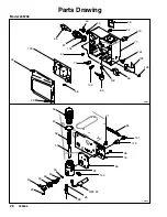
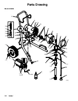
Refer to Fig. 6--9.
Relieve pressure; page 5.
1. Remove four screws (23) and cover (56).
2. Disconnect lead (E) from control board (100).
3. Disconnect hose (65). Remove three screws (98)
and filter housing (69). Refer to page 28.
4. Thread transducer lead (E) plastic connector
through transducer grommet (124).
5. Remove pressure control transducer (68) and
o-ring (26) from filter housing (69).
Installation
1. Install o-ring (26) and pressure control transducer
(68) in filter housing (69). Torque to 30--35 ft-lb.
2. Thread transducer lead (E) plastic connector up
through transducer grommet (124).
3. Install filter housing (69) with three screws (98).
Connect hose (65).
4. Connect lead (E) to control board (100).
5. Install cover (56) with four screws (23).
Pressure Adjust Potentiometer
Removal
Refer to Fig. 6--9.
Relieve pressure; page 5.
1. Remove four screws (23) and cover (56).
2. Disconnect all leads from control board (100).
3. Remove five screws (38) and board (100)
4. Remove potentiometer knob (36), sealing shaft nut
(32) and pressure adjust potentiometer (64).
5. Remove and save panel nut (133).
Installation
1. Install panel nut (133) on potentiometer (64).
2. Install pressure adjust potentiometer (64), sealing
shaft nut (32) and potentiometer knob (36).
a
.
Turn potentiometer fully clockwise.
b
.
Install knob at full clockwise position.
3. Install board (100) with five screws (38).
4. Connect all leads to control board (100).
5. Install cover (56) with four screws (23).
Содержание 246796
Страница 19: ...19 309902 Wiring Diagram Model 249308 6489A Fig 9 ...
Страница 35: ...35 309902 Notes ...


