


Installation Manual 381333-445
ASCO 4ATE, 4ACTE, 4ADTE, 4NTE, 4NCTE, 4NDTE
381333-445 B
ASCO Power Technologies
Page 7
Bypassing & Isolating
The Bypass Switch (electrically-operated) is controlled by a
bypass-isolation controller (Figure 4). It provides status lights
and push-button operation of the Bypass Switch.
Bypass & Isolation Status
Light
Function
Normal
Available
ON if both normal source voltage & frequency are above
pickup points. OFF if either is below the dropout points.
Emergency
Available
ON if both emergency voltage & frequency are above
pickup points. OFF if either is below the dropout points.
Load Energized
Green if load is connected to normal source & available.
Red if the load is connected to emergency & is available.
OFF if load de-energized.
Bypassed to
Normal
ON when the Bypass Switch is closed on normal.
OFF when the Bypass Switch normal contact is open.
Bypassed to
Emergency
ON when the Bypass Switch is closed on emergency.
OFF when Bypass Switch emergency contact is open.
Connected
ON when ATS is connected.
Test
ON when ATS is in test..
Isolated
ON if ATS is Isolated.
ATS on Normal
ON when the ATS is closed on the Normal source.
ATS on
Emergency
ON when the ATS is closed on the Emergency source.
OK to Connect
or Disconnect
ATS
ON when the ATS can be connected or disconnected
(isolation handle can be turned to
TEST
,
CONN or ISO
)
Alarm
Blinks yellow when an alarm condition is present
Not in
Auto
Blinks yellow when the ATS is not in an automatic
operation mode (bypassed or rack not connected)
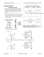
Allowable Positions of the Bypass Switch
in relation to Positions of the Transfer Switch
If Transfer Switch is Connected
and in this position
Bypass Switch
can be in either
Normal open
Normal
Emergency open
Emergency
Bypass Controls
Light
Function
Bypass
Restricted
Flashes if the wrong
Bypass to
button is pressed or the
Permitted
light is off.
ON solid is an alarm (see troubleshooting).
Permitted
ON if bypassing to that source (N or E) is allowed.
OFF if bypassing to that source is not allowed.
Engine Control
Light
Function
Manual Engine
Start Active
ON if the Engine Control is in the RUN position.
NOTE:
The automatic controls will only allow the bypass
to connect to the same source as the ATS.
Figure 4. Bypass-Isolation Controller lights & controls
Close enclosure door to prevent personal injury in
case of electrical system fault.
Source Voltage & Frequency
Availability Points
Normal Emergency
V
ca
Drop Out
85%
80%
V
ca
Pick Up
90%
90%
Frequency Drop Out
85%
85%
Frequency Pick Up
86%
86%
Availability is determined by monitoring the Voltage across
the C & A phases to ensure it meets the below parameters
relative to the nominal voltage. It is only meant to indicate if
there is sufficient power to operate the Bypass Switch and
does not represent acceptability of the source relative to the
loads.
Isolation Contacts
Bypass Switch


