


ASCO 4ATE, 4ACTE, 4ADTE, 4NTE, 4NCTE, 4NDTE
Installation Manual
Page 18
ASCO Power Technologies
381333-445 B
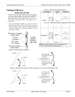
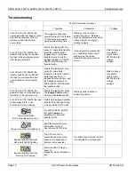
Troubleshooting
r
Check in Numerical Sequence
1 Operation
2 Generator
3 Voltage
For 4ATE, 4ACTE, 4ADTE the
engine-generator set does not start
when the transfer test button is
pressed or when the Normal
source fails.
The outage must be long
enough to allow for the feature
1C time delay plus engine
cranking and starting time.
Starting control must be in
automatic position. Batteries
must be charged and connected.
Check wiring to the engine
starting contacts.
-
For 4ATE, 4ACTE, 4ADTE the
transfer switch does not transfer
the load to the emergency source
after the gen-set starts.
Wait for the feature 2B time
delay. For immediate transfer,
press the transfer button
(bypass timer). If inphase
transfer is active, wait for
inphase condition. For 4NTE,
4NCTE, 4NDTE press the
transfer button.
Is the generator accepted light
on? Generator output circuit
breaker must be closed.
Generator frequency must be
correct.
Refer to Group
H controller
User’s Guide
381333-444 for
voltage
settings.
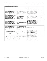
For 4ATE, 4ACTE, 4ADTE the
transfer switch does not transfer
the load to normal source when
normal returns or after transfer
test.
Wait for the feature 3A time
delay. For immediate
retransfer, press the transfer
button (bypass timer). If
inphase transfer is active, wait
for inphase condition. For
4NTE, 4NCTE, 4NDTE press
the transfer button.
-
Refer to Group
H controller
User’s Guide
381333-444 for
voltage
settings.
For 4ATE, 4ACTE, 4ADTE the
generator does not stop after load
retransfer to the normal source.
Wait for the feature 2E delay.
The
Engine Control
switch
must be in the
Auto
position.
Starting control must be in
automatic position.
-
For 4ATE, 4ACTE, 4ADTE the load
is deenergized (off).
Load
Disconnect Timer
on display.
Wait for the delayed-transition
transfer timer. See the Group
H User’s Guide 381333-444.
-
Group H controller
Not in Auto light is always on.
For 4NTE, 4NCTE, 4NDTE
this light is always on,
indicating it is a manual
transfer switch.
- -
Group H controller Alert light is on.
Read the display for more
information. Refer to
User’s Guide 381333-444.
- -
Bypass-Isolation controller
Not in Auto light is flashing.
The ATS is not in an
automatic operation mode
because it is bypassed or
isolated (not connected).
The light will go off when the ATS
is connected and un-bypassed.
Bypass-Isolation controller
alarm light is flashing.
Alarm condition (1 flash a
second)
Diagnostic mode (5 flashes a
sec.)


