background image

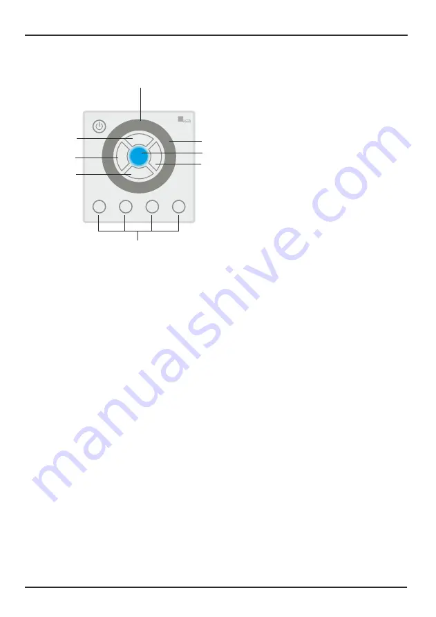
1. Power key
    

Used to power on/off  DLC-4.


7. Touch toggle

    Used to adjust color, brightness and speed, and select built-in programs. 

5. B key

 (brightness)

    Used to adjust brightness.
     

2. C key

 (color)

    Used to select color. 

3. P key

 (program)

    Used to select Built-in program.

4. S key 

(speed)

    Used to adjust speed.

6. Output Indicator

    Used to display the current output.

8. Figure keys (1~4)

    Used to record scene and color, as well as set fadetime.

Figure 1

DLC-4 features one group DMX OUT with 4-pin terminal connector, one group 
POWER IN & PWM  OUT with 6-pin terminal connector. The configuration of 
the terminal is as the following(figure 2):

1. (4-pin terminal) LINK IN 
2. (4-pin terminal) DMX OUT 
3. (6-pin terminal) PWM OUT & POWER-IN 
1. (4-pin terminal) LINK OUT

Page 2

DLC-4 User Instruction

Page 3

DLC-4 User Instruction

Control Panel and Functions

Rear Panel View

Installation

Connect the POWER IN to  a 12-24V DC Powersupply 
and connect the PWM OUT to the RGB fixture(s)
max. load is 6A;

at 12V load max.   72W (3x 24W)

at 24V load max. 144W (3x 48W)

 If needed more than 6A, connect the DMX-OUT to the   
 next DMX-dimmerpack(s) LED-Domotion 3 (A9915015)

 Note:

 The DLC-4 will cover and can be 
 mounted on a European wallbox.

  Mounting on a wallbox:
     1. Remove screws   & 

A

B

     2. Remove the cover and mount the controller.
     3. Mount the cover with screws    & 

A

B

60mm

C

P

B

S

1

2

3

4

DLC-4

Domotion DLC-4

DMX-out

12-24V DC

RGB Light Fixtures (max.6A)

RGB Light Fixtures

(Domotion) 
DMX Dimmerpack

12-24V DC 
Powersupply

Figure 2

LINK IN

DMX OUT

LINK OUT

DC IN

PWM OUT

Made in P.R.C.

24-005-1396-01

GND

D-

D+

V+

GND

D-

D+

V+

GND

D-

D+

B

V+

G

R

GND

V in+

V+

1

2

3

4

C

P

B

S

1

2

3

4

DLC-4

2

3

4

1

5

6

7

8

Dimensions in mm

85x85

30

15.5

wallbox

wall

Link-
IN

DMX-
OUT

DC-IN
PWM-out

Link-
OUT

Remove screws A & B for mounting on a wallbox

A

B

Содержание Domotion DLC-4 RGBW

Страница 1: ...INSTRUCTIONS MANUAL Please read this manual carefully and thoroughly before operating this unit DLC 4 C P B S 1 2 3 4 DLC 4 ...

Страница 2: ...ON OFF 4 2 Built in Program 5 3 Brightness 5 4 Speed 5 5 Color 6 6 SCENE 7 7 Key Tone 8 8 Default Setting 8 Physical Dimensions 9 Technical Specification 9 Operation Guide 4 8 5 1 Recording Color 6 5 2 Playback Color 6 5 3 Setting Fadetime for Color Exchange 6 6 1 Recording SCENE 7 6 2 Playback SCENE 7 6 3 SCENE Record Lock Unlock 7 ...

Страница 3: ...r any transport damage after unpacking the equipment inform the hauler immediately Never connect a damaged device You may also contact your supplier LED indicator to display the current output Four function menus To record and play back upto 4 scenes and 4 colors To set fadetime for Power on off and color exchange in the range of 0 to 4s To assign key tone ON OFF To select input voltage in DC12 24...

Страница 4: ...brightness 2 C key color Used to select color 3 P key program Used to select Built in program 4 S key speed Used to adjust speed 6 Output Indicator Used to display the current output 8 Figure keys 1 4 Used to record scene and color as well as set fadetime Figure 1 Page 2 DLC 4 User Instruction Control Panel and Functions C P B S 1 2 3 4 DLC 4 2 3 4 1 5 6 7 8 ...

Страница 5: ...4W 3x 48W If needed more than 6A connect the DMX OUT to the next DMX dimmerpack s LED Domotion 3 A9915015 Note The DLC 4 will cover and can be mounted on a European wallbox Mounting on a wallbox 1 Remove screws A B 2 Remove the cover and mount the controller 3 Mount the cover with screws A B 60mm C P B S 1 2 3 4 DLC 4 Domotion DLC 4 DMX out 12 24V DC RGB Light Fixtures max 6A RGB Light Fixtures Do...

Страница 6: ...atically All indicators flash momentarily once to confirm the setting Touch any one of these keys 1 2 3 4 P C B or S To set power on off fadetime follow the procedures below Setting Shortcut for Power ON OFF To delete power shortcut touch P key and Power key simultaneously and hold on for about 10 seconds until all keys flash once Touch Power key once DLC 4 changes to standby condition Directly to...

Страница 7: ...decreases 4 Speed When you rotate the toggle to reach 10min the click disappears and all the four figure keys flash repeatedly Then you select the speed which you wish by pressing any of the figure keys Different figure keys stand for different speed 1 for 10min 2 for 20min 3 for 30min and 4 for 40min Press S key to enable Speed Menu the key clicks and the indicator lights up Then rotate the touch...

Страница 8: ...ch toggle to adjust RGB value until you get desired color b d e Touch C key to enable Manual Mode Then touch the corresponding button of 1 4 to raise the color which you ve stored in the key The LED indicator lights up and it starts to display the recorded color 5 1 Recording Color 5 2 Playback Color 5 3 Setting Fadetime for Color Exchange Touch C key and hold on for 5 seconds till all LED indicat...

Страница 9: ...ouch any of the figure keys to which you wish to record the scene and hold on for more than 2 seconds a b c d Rotate the touch toggle to select the built in program or adjust the speed e Touch P or S key to enable Auto Mode Then touch the corresponding button of 1 4 to raise the scene which has been stored in it The LED indicator lights up and it starts to display the recorded scene 6 2 Playback S...

Страница 10: ...ppears With key tone OFF when you rotate the touch toggle to the maximum or minimum value all keys flash repeatedly 3 times 7 Key Tone 8 Default Setting Page 8 DLC 4 User Instruction Operation Guide Touch P key and B key simultaneously and hold on for about 10s until all keys flash once to resume default setting All the settings by the user are deleted The fadetime for color change and power ON OF...

Страница 11: ...Temperature Storage Temperature Weight Dimension DC 12 24V 2A per channel 6A in total Polycarbonate 4 pin green terminal 6 pin green terminal 0 degC to 40 degC 20 degC to 70 degC US 150g EU 100g EU 86 L x86 W x15 5 H mm US 76 L x120 W x15 5 H mm Page 9 DLC 4 User Instruction Physical Dimensions ...

Страница 12: ...DLC 4 User Instruction All rights reserved Any improvement and changes to specifications design and this manual may be made at any time without prior notice ...

Отзывы: