


ARS RECYCLING SYSTEMS
DC Manual 20190729
Page | 11
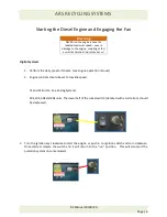
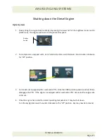
Shutting down the Diesel Engine
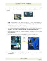
Digital Systems
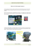
1.
Slowly bring the engine back to idle by depressing the lower half of the high/low rocker switch
(turtle icon). The engine will return to the preset idle speed.
2.
For compressor equipped units, turn Pulsation System
and
Aftercooler knob counter-clockwise
for “off” position.
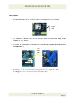
3.
For models not equipped with an automatic PTO: Once the 1000 rpm idle speed is reached, firmly
disengage the PTO. If the engine is equipped with an automatic PTO, simply let the engine idle
until cool.
4.
Once the engine has cooled to normal operating temperature, it may be shut down.
Turn the key/ignition switch counter-clockwise to the “off” position. Key may now be removed.
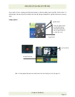
Rocker
Switch


