Overview
BeMicro Max 10 Getting Started User Guide, Version 14.0
4
1.3 Getting To Know Your Kit
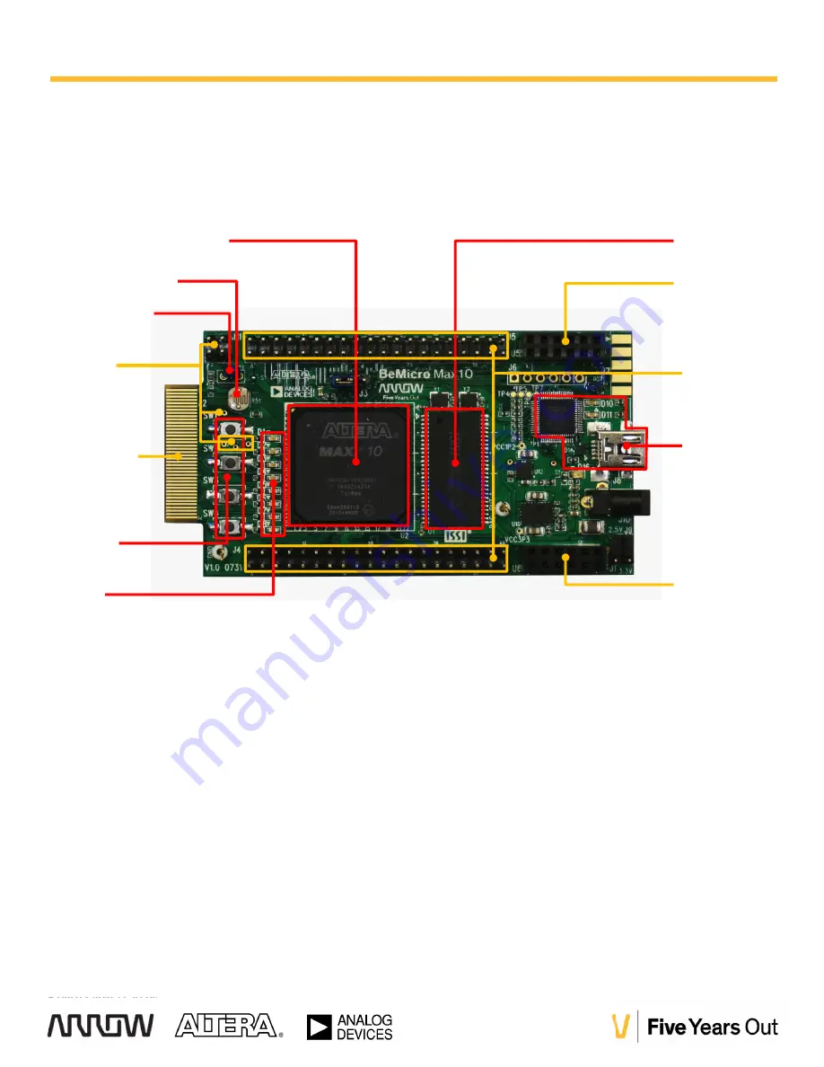
Below is an annotated photo of the board to help you get familiar with the kit and locate the various peripherals and
expansion connectors.
Figure 1-2: BeMicro Max 10 Development Kit
Altera MAX 10 FPGA
10M08DAF484C8GES
8MB SDRAM
Push
Buttons
LEDs
Photo Resistor
Thermistor
80-pin
BeMicro
Edge
Connector
Analog
Inputs
PMOD A & B
PMOD C & D
USB Blaster
Two 40-pin
Expansion
Headers
Accelerometer
(U3 on back)
Temperature Sensor
(U7 on back)
12-bit DAC
(U4 on back)
Your BeMicro Max10 is preloaded with a simple design which can be used to confirm that your kit is operational upon
power up.
Connect your BeMicro Max10 board to any USB power source(PC or USB charger) and watch the LED1 shine.
Put your finger on the Analog Devices ADT7420 temperature sensor and watch the LEDs change intensity.
(Your finger need to be somewhat close to body temperature.) The temperatures sensor device is component
U7 on the back of the board.
1.3.1 Powering the BeMicro MAX 10
The BeMicro MAX 10 is powered through the USB connection provided for the USB-Blaster functionality. If you wish
to run the board stand-alone, you will need to source a 5V power supply with a 2.5mm jack. This optional power
supply is not included with the kit.


