


page 40 / 75 0MNA080A55-GB REV 01
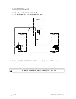
J1
J2
J3
SW1
J1
J2
J3
SW1
LED
LED
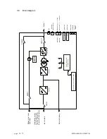
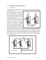
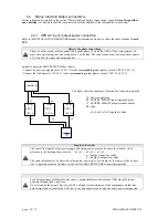
4.4
Connection of signals
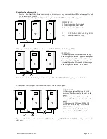
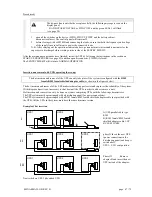
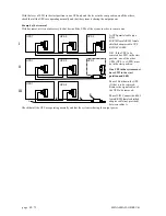
The signals of several parallel UPSs are connected in a closed loop configuration; if the loop is interrupted at any
point, either due to a fault or for maintenance, operation of the system is not compromised, and the system continues
to operate normally, as will be shown repeatedly below.
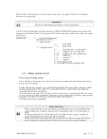
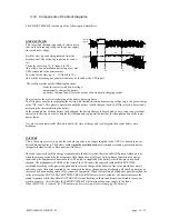
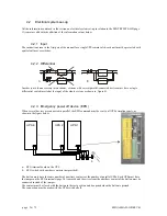
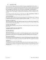
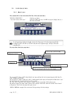
The various UPSs are connected through the “signals RJ45-flat-
adapter” parallel card, located in the lower part of the UPS (in
the area for signal and command connections as shown in the
section on SIGNALS and REMOTE COMMANDS).
- RJ45-flat-adapter signals parallel card.
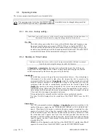
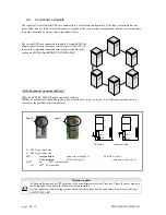
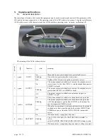
N.B.:
the SENTRY MPS-HP may be provided with two
versions of parallel card that differ in the type of switch used (type 1 or type 2). The difference between the two
switches is the position of the control lever.
Type 1
type 2
LED side
connector side
J1 RJ45 type connector
J2 RJ45 type connector
SW1
start position
connector side(type 1)
LED side (type 2)
Cont
position
LED side (type 1)
connector side (type 2)
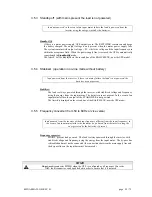
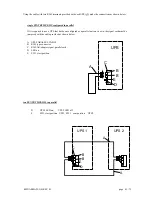
LED
on
SW1 start position
off
SW1
Cont
position
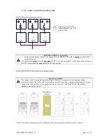
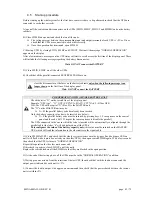
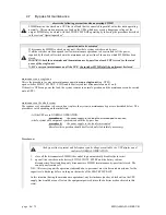
Firmware update
All the parallel-connected UPSs must have the same firmware version. Press key 7 from the basic menu on
the display panel to display the firmware version installed.
For the expansion of an existing system, check that the system has the same firmware version as the new
SENTRY MPS-HP.
Содержание SENTRY MPS-HP
Страница 25: ...0MNA080A55 GB REV 01 page 25 75 Page blank ...
Страница 49: ...0MNA080A55 GB REV 01 page 49 75 Page blank ...
Страница 69: ...0MNA080A55 GB REV 01 page 69 75 Page blank ...
Страница 70: ...page 70 75 0MNA080A55 GB REV 01 Page blank ...


