


page 16 / 75 0MNA080A55-GB REV 01
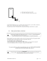
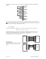
3.1.4 Battery
Battery cabinet
For connection to the UPS, the battery cabinet must have an overcurrent protection device and a
disconnecting device.
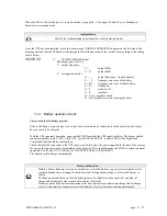
The disconnector may be closed
only when
the UPS is started up regularly; see the section “Start-up
procedure” on page 26.
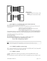
The function of the fuses is to protect the batteries and the cables from a shortcircuit between the battery cabinet and
the UPS. The following rules should be observed for their sizing:
•
if rapid fuses of the type gl / gG are installed
: the maximum size of fuse to be used is 2 times the
battery capacity in Ah.
•
If ultra rapid fuses of the type aR are installed
: the maximum size of fuse to be used is 2.5 times
the battery capacity in Ah.
For example: the following fuses may be used for batteries of the type 150Ah: 250A type gl/gG or 315A type aR.
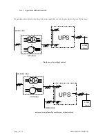
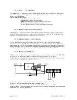
3.1.5 Backfeed protection
The SENTRY MPS-HP is provided with a device to prevent voltage backfeed on the input line due to an internal
fault. This protection device works by switching off the inverter if the current flow is faulty, thereby causing voltage
backfeed on the by-pass line during operation from the inverter. If the fault occurs when the UPS is operating from
the battery, the load will not be powered.
Should it be required to avoid the shutting down of the inverter in order to keep the load powered by the inverter
even in the event of a double fault, the system can be customized to control the opening coil of a switch located
upstream by reprogramming one of the relays on the “REMOTE COMMANDS AND ALARMS” card.
The control logic allows the function of the relay to be reconfigured, for example for the backfeed alarm, and then
the free voltage contact can be used to control the triggering of a switch located on the UPS input.
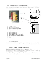
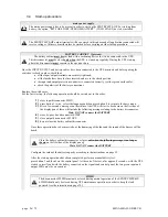
3.1.6 Emergency power off device (EPO)
The UPS is pre-set to be connected to a remote emergency power off device as laid down in standard EN 62040-1-
2. If the remote device (not supplied with the equipment) is activated, the inverter output voltage is cut.
The connection procedure is shown below.
Содержание SENTRY MPS-HP
Страница 25: ...0MNA080A55 GB REV 01 page 25 75 Page blank ...
Страница 49: ...0MNA080A55 GB REV 01 page 49 75 Page blank ...
Страница 69: ...0MNA080A55 GB REV 01 page 69 75 Page blank ...
Страница 70: ...page 70 75 0MNA080A55 GB REV 01 Page blank ...


