background image

High Limit Humidistat

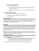
Remove the jumper tab from ground and in of high limit/pressure switch connections and wire the high
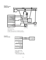
limit stat between these terminals. Refer to Figure10-1 (the overall wiring diagram) for more inform
ation. A duct mounted high limit humidistat is recommended to prevent over-saturation of the duct air.
Use an on-off controller that opens on fault (high humidity). Humidistat should be set for a maximum 
of 90% RH. Alternately, a modulating high limit humidistat may be used on applications such as 
variable air volume (VAV). Locate the high limit humidistat approximately 3m (10 feet) downstream of
the dispersion manifold. If 3m (10 feet) is not available, consult the factory. Note: High limit humidistat
will be wired in series with duct pressure switch, if used, see Figure 10-1.

Airflow/Pressure Switch

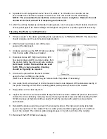
An airflow switch is recommended to deactivate the humidifier when there is insufficient air flow in a
duct system. A duct pressure switch is preferred as an airflow sensor. The pressure switch should
open on insufficient airflow (opens on fault). Airflow switch should be mounted in supply air duct
upstream of humidifier dispersion. Remove the jumper tab from ground and in of high limit/pressure
switch connections and wire the airflow sensor between these terminals. See Figure 10-1 (the overall
wiring diagram) for more information. Complete installation and wiring instructions are contained in the
duct pressure switch package. 

Note: 

Duct pressure switch will be wired in series with high limit

humidistat, if used, see Figure 10-1.

State light will flash green if either high limit or air pressure switches are open.

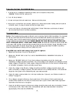
Alarm Circuit

The terminals 3 & 4 (normally open relay external alarm) are connections for a class II NEC alarm 
circuit (switch closure only, 1 amp. maximum @ 24 Vdc or 0.5 amp. @ 125 Vac). The switch will close
if the unit encounters an error or when service life has expired it will not engage if high humidity/sail
switch circuit is open.

12

Содержание HumidiClean HC-6100 Series

Страница 1: ...ge Warning Labels 2 3 Description of Model Number 4 Installation 6 12 Display Menu 13 16 Start Up Procedure and Operation 16 17 Maintenance 18 22 Troubleshooting 22 27 Typical Wiring Schematic 28 37 R...

Страница 2: ...RCUIT BREAKER OR SAFETY SWITCH BEFORE OPENING ANY COVERS AND DOORS 3 Before servicing the humidifier learn where the high voltage parts are KEEP HANDS AND METAL TOOLS AWAY FROM THESE AREAS Warning All...

Страница 3: ...ply and have one OFF isolated and one ON position only clearly marked with O and I symbols 60417 2 IEC 5008 and 60417 2 IEC 5007 see 10 2 2 with the actuating directions in accordance with IEC60447 Ci...

Страница 4: ...nt A claim should be filed with the transportation company and reported to Armstrong if any items are missing or damaged 2 Check Local Codes The installation of HumidiClean should be in accordance wit...

Страница 5: ...Detail A Pitch Min 1 Per 12 Back to Unit P Trap Drain Every 20 of Piping or at Bottom of Vertical Run 24 2 Insulated Copper 24 1 Copper Min Pitched 1 Per 12 Min to Open Drain 1 ID Hose Air Gap Fused...

Страница 6: ...ny potable or purified water supply Water pressure must be 25 120 psig Water temperature must be less than 60 C 140 F 1 Install a shut off valve near the unit 2 Connect the water supply to the 3 8 com...

Страница 7: ...Steam Output kg hr lb hr Steam Output kg hr lb hr Nominal Amperage Rating Three Phase Steam Output kg hr lb hr Nominal Amperage Rating Three Phase Steam Output kg hr lb hr Nominal Amperage Rating Thr...

Страница 8: ...ipe and hose cuffs provided We do not suggest steam distribution piping of field supplied rubber based compounds to be used for any HumidiClean application Pitch pipe back to unit 25 mm 1 per foot The...

Страница 9: ...o keep the electric cabinet in compliance with IP32 Wiring for low voltage controls should not be run in same conduit as the power supply Use of shielded wire or a separate dedicated metal conduit is...

Страница 10: ...Switch To Set Up 1 S1 1 3 Off S1 2 On 2 S3 1 On S3 2 3 4 Off 3 S2 1 2 3 Off 4 Select 0 10vdc Signal Type in the Operational Setup Menu 5 Select Humidistat Sensor Select in the Operational Setup Menu F...

Страница 11: ...4 2 on S4 1 3 Off S3 1 on S3 2 3 4 off 24Vac S4 1 3 on S4 2 Off S3 2 on S3 1 3 4 off 10Vac S4 1 3 on S4 2 Off S3 3 on S3 1 2 4 off 5Vac S4 1 3 on S4 2 Off S3 4 on S3 1 2 3 off 4 on 5 off Thermistor 4...

Страница 12: ...n there is insufficient air flow in a duct system A duct pressure switch is preferred as an airflow sensor The pressure switch should open on insufficient airflow opens on fault Airflow switch should...

Страница 13: ...Unit configuration setup English English Default Chinese Unit Status 1 Unit Demand XXX Demand Steam Output XXX lb hr Steam Output Unit Status 2 Water Level Normal Water Level State Low Normal and High...

Страница 14: ...ure of water 180 F 80 C The maximum is 80 C 180 F the minimum is 4 C 40 F If the set point is lower than 40 F then function is disabled When disabled the unit will go into a 3 minute warm up when turn...

Страница 15: ...15 Default PID Settings PB Proportion Brand 0 900 PID PB 10 PID IRV 10 IRV Integral Reset Value 0 500 PIDF DG 200 PID SI 10 DG Derivative Gain 0 500 SI Interval 0 30 Records Error List 01 05 04 01 16...

Страница 16: ...ectrical compartment for any loose or disconnected component wiring Check all high voltage screw terminal connections at contactor terminal strip fuse block power module for tightness 2 Remove Side Pa...

Страница 17: ...read from the humidistat or calculated by reading the relative humidity and setpoint If the demand sig nal drops below 2 or the high limit sail switch circuit opens the contactor s will open and the u...

Страница 18: ...bed does not appear to be saturated with mineral deposit a full bed will weigh 1 1 kg 2 6 lbs dry and if the drain screen is clear you have two options a Reset the Ionic Bed service life Proceed with...

Страница 19: ...PERATION section after the HumidiClean has accumulated 90 of the selected Service Life in hours of heater on time the STATE LED will flash blink in yellow At this time the ionic beds in the tank shoul...

Страница 20: ...Make sure access panel gasket is lapped over all edges of tank access opening Replace and secure tank access panel 7 Make sure both access doors panels are secure 8 Turn on power at circuit breaker 2...

Страница 21: ...ng the probe and wire locations Note Level control float switches are used for DI RO or very pure water Cleaning should not typically be required 5 Unscrew the probes from the level canister using the...

Страница 22: ...midification Group at Phone 269 273 1415 Humidifier will not fill with water when power is applied 1 Make sure the status in menu is Steam Gen 2 Make sure STATE LED is red If so refer to MAINTENANCE o...

Страница 23: ...s OK the PC board is likely defective b If voltage is 17 20 VAC with circuit open but does not drop when water contacts the two electrodes the water may be too pure consult factory or if the voltage d...

Страница 24: ...float lever arm swings freely 2 The fill valve may be stuck open Turn off power to the humidifier If fill valve does not close clean or replace valve 3 If the high water circuit is closed and the fil...

Страница 25: ...mately 8 with wires disconnected If resistance is OK check voltage drops across the contactor b If no voltage to contactor coil check continuity of wires from PC board to contactor If continuity is OK...

Страница 26: ...RH A high limit humidistat RH sensor is recommended to prevent this See Installation section Water in bottom of cabinet 1 Verify that pressure equalizing tubing is hooked up from top of electrode lev...

Страница 27: ...rnal temperature exceeds safe level Check low water in tank scale buildup on Thermocouple heating element surface defective Thermocouple See Clearing Error Codes section 6 WATER LEVEL HAS NOT DROPPED...

Страница 28: ...HC6100 Wye Wiring layout 28...

Страница 29: ...HC6100 Delta Wiring layout 29...

Страница 30: ...30 HC6100 PAR Single Phase Wiring Layout...

Страница 31: ...HC6300 Wye Wiring layout 31...

Страница 32: ...HC6300 Delta Wiring layout 32...

Страница 33: ...HC6500 Wye Wiring layout 33...

Страница 34: ...HC6500 Delta Wiring layout 34...

Страница 35: ...35 HC6500 WYE 2 contactors Wiring Layout...

Страница 36: ...36 HC6500 Delta 2 contactors Wiring Layout...

Страница 37: ...HC6700 Wye Wiring layout 37...

Страница 38: ...DM hose cuff B2851 1 1 2 IDx9 5 8 EPDM hose cuff B2250 1 IDx18 EPDM hose cuff A9620 1 Hardware Assembly B5287 Passivated Tank D2171 25 S assy Ionic Bed HC 6000 six required for HC 6100 and HC 6300 B52...

Страница 39: ...B5045 2 B5046 2 380 B5049 1 B5050 1 B5045 1 B5046 1 480 B5049 3 B5050 3 B5045 3 B5046 3 600 B5049 4 B5050 4 B5045 4 B5046 4 Without TC 5PCS Unit With TC 1PCS Unit Without TC 5PCS Unit With TC 1PCS Uni...

Страница 40: ...A7618A Clamp Hose Flat 63 Olive B2716 11 Hose Clamp Minerature Worm B2911 8 25 Fill Valve RDHC6000 001 21 Tubing Rd 7 8 Od Silicon A19699 23 Clamp Hose Flat 88 B2716 18 22 Tee Barbed HDPE 5 8 A23237...

Страница 41: ...c 14 5 16 8 277Vac 24 across H1 H4 600Vac 15 30kW 346Vac 22 7 26 3 380Vac 40 across H1 H5 208Vac and 380Vac9 18kW 220Vac 15 3 17 7 480Vac 53 across H1H6 240Vac 9 18kW 240Vac 18 2 21 1 600Vac 97 across...

Страница 42: ...out TC 5PCS Unit With TC 1PCS Unit Without TC 5PCS Unit With TC 1PCS Unit Without TC 5PCS Unit With TC 1PCS Unit Without TC 8PCS Unit With TC 1PCS Unit B5435 1 B5436 1 B5435 1 B5436 1 B5435 1 B5436 1...

Страница 43: ...rgency button The indicator LED D47 on main board will remain ON Keep the power supply on for at least 8 seconds This is the step to erase the old code c Turn off the power supply and put dip switch S...

Страница 44: ...pen folder button on the right of textbox Send File Name to open the latest code please see figure 3 below You will then have to locate the bin file that you downloaded from the website and then hit o...

Страница 45: ...de into board Please see figure 4 below Fig 4 Message Unlock Involved Lock Regions Window f When sending was finished you will be asked to lock all locks that you have opened just now click the button...

Страница 46: ...ect different port Please see instruction details for Modbus_RTU used in HC6000 When you want to use modules please change the configuration from communication to PSP per menu See section 3 2 3 commun...

Страница 47: ...ime out from low to high level 8 Water level above high level time out 9 Water level has not dropped below low level during an emptydrain 10 End of bed dring 30019 Contactor number 30020 Contactor Pow...

Страница 48: ...rcuit is open 3 Illegal level switch state 4 Unit have reached 100 of bed life 5 Fill time out to low level 6 Water level dropped below level during normal run 7 Fill time out from low to high level 8...

Страница 49: ...O Server Lon_1 SNVT_temp_p oOUTRH_L SINTB 5 NVPO Server Lon_1 SNVT_lev_percent oRUN_MODE SINTB 6 NVPO Server Lon_1 SNVT_count_f oWATER_TEMP_SET SINTB 7 NVPO Server Lon_1 SNVT_temp_p oBED_LIFE SINTB 8...

Страница 50: ...5 D Drain Back 20 508 29 3 16 748 E Drain Side 9 1 8 232 11 1 2 293 F Steam Discharge Tube 2 3 8 60 2 3 8 60 G Steam Outlet Side 7 1 2 190 9 1 2 241 H Steam Outlet Front 14 1 3 364 12 7 8 328 J Supply...

Страница 51: ...6700 Front Side Top Views Q B G A D E Water Supply Port Under Cabinet H J K L M C F Electrical Supply Under Cabinet 1 Drain Under Cabinet Knock Out for Humidistat Knock Out for Humidistat Physical Dat...

Страница 52: ...er basis or theory is limited to Armstrong s repair or replacement of the part or product excluding any labor or any other cost to remove or install said part or product or at Armstrong s option to re...

Отзывы: