


Issue 1324
507120-01
Page 4 of 18
Installation Clearances
NON-DUCTED RETURN CLOSET INSTALLATION
The air handler can be installed in a closet with a false bot-
tom to form a return air plenum. It may also be installed with
a return air plenum under the air handler.
Louvers or return air grilles are field supplied. Local codes
may limit application of systems without a ducted return to
single story buildings.
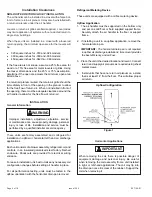
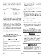
When these unit are installed in a closet with a louvered
return opening, the minimum open area for the louvers will
be:
•
320 square inches for -018 and -024 models;
•
360 square inches for -030 and -036 models;
•
450 square inches for -042 thru -060 models.
If the free area is not known, assume a 25% free area for
wood or a 75% free area for metal louvers or grilles. Using
the louver dimensions and the 25% or 75% assumption,
determine if the open area meets the minimum open area
listed above.
If a return air plenum is used, the return air grille should be
immediately in front of the opening in the plenum to allow
for the free flow of return air. When not installed in front of
the opening, there must be adequate clearance around the
air handler to allow for the free flow of return air.
These
units are factory assembled and configured for
installation in upflow or horizontal left hand air discharge
applications.
Each unit consists of a blower assembly, refrigerant coil, and
controls, in an insulated galvanized steel factory finished
enclosure. Knockouts are provided for electrical wiring
entrance.
For ease in installation, it is best to make any necessary coil
configuration changes before setting air handler in place.
For all performance testing, units must be tested in the
upflow orientation with the horizontal drain pan removed.
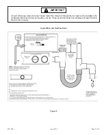
Refrigerant Metering Device
These units are equipped with a orifice metering device.
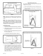
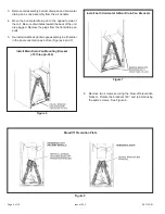
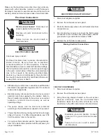
Upflow Application
1. The air handler must be supported on the bottom only
and set on solid floor or field supplied support frame.
Securely attach the air handler to the floor or support
frame.
2. If installing a unit in an upflow application, remove the
horizontal drain pan.
IMPORTANT:
The horizontal drain pan is not required
in upflow air discharge installations; its removal provides
the best efficiency and air flow.
3. Place the unit in the desired location and level it. Connect
return and supply air plenums as required using sheet
metal screws.
4. Install units that have no return air plenum on a stand
that is at least 14” from the floor. This will allow proper
air return.
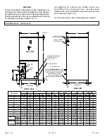
INSTALLATION
General Information
Horizontal Applications
Figure 1
Upflow Configuration
Improper installation, adjustment, alteration, service
or maintenance can cause property damage, personal
injury or loss of life. Installation and service must be
performed by a qualified installer or service agency.
WARNING
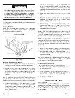
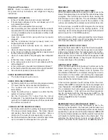
When removing the coil, there is possible danger of
equipment damage and personal injury. Be careful
when removing the coil assembly from a unit installed
in right- or left-hand applications. The coil may tip into
the drain pan once it is clear of the cabinet. Support the
coil when removing it.
IMPORTANT
Содержание BCE3M 18
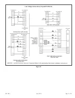
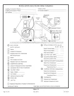
Страница 11: ...Page 11 of 18 Issue 1324 507120 01 Figure 12 Low Voltage Connections 3 Speed PSC Motor...
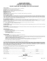
Страница 15: ...Page 15 of 18 Issue 1324 507120 01 Start Up and Performance Checklist Horizontal Configuration Figure 14...
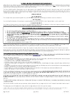
Страница 16: ...Issue 1324 507120 01 Page 16 of 18 Figure 15 Start Up and Performance Checklist Upflow Configuration...


