


Issue 1324
507120-01
Page 10 of 18
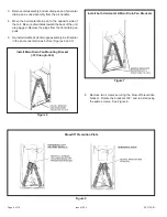
Make sure the liquid line and suction line entry points are
sealed with either Armaflex material or with Permagum.
Permagum may also be used to seal around the main and
auxiliary drains and around open areas of electrical inlets.
Electrical Connections
Electric shock hazard!
- Disconnect all
power supplies before servicing.
Replace all parts and panels before
operating.
Failure to do so can result in death or
electrical shock.
WARNING
•
All field wiring must be done in accordance with National
Electrical Code, applicable requirements of UL and local
codes, where applicable.
•
Electrical wiring, disconnect means and over-current
protection are to be supplied by the installer. Refer to
the air handler rating plate for maximum over-current
protection, minimum circuit ampacity, as well as
operating voltage.
•
The power supply must be sized and protected
according to the specifications supplied on the product.
•
This air handler is factory-configured for 240 volt, single
phase, 60 cycles. For 208-volt applications, see “208
Volt Conversion” later in this section.
•
For optional field-installed electric heat applications,
refer to the instructions provided with the accessory for
proper installation.
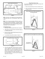
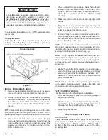
1. Disconnect all power supplies.
2. Remove the air handler access panel.
3. Route the field supply wires to the air handler electrical
connection box.
4. Use UL-listed wire nuts to connect the field supply
conductors to the unit black and yellow leads, and the
ground wire to ground terminal marked “GND.”
5. Replace the air handler access panel.
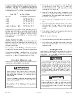
208 VOLT CONVERSION
1. Disconnect all power supplies.
2. Remove the air handler access panel.
3. Using the wiring diagram located on the unit access
panel as a reference, move the 2 connected black
transformer leads from the 240 volt terminal on the
transformer to the 208 volt terminal on the transformer.
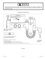
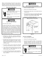
Making Electrical Connections
Figure 11
WARNING
ELECTRIC SHOCK HAZARD
Can cause injury or death.
Foil-faced insulation has conductive characteristics
similar to metal. Be sure there are no electrical
connections within a 1/2” of the insulation. If the foil-
faced insulation comes in contact with electrical voltage,
the foil could provide a path for current to pass through
to the outer metal cabinet. While the current produced
may not be enough to trip existing electrical safety
devices (e .g. fuses or circuit breakers), the current can
be enough to cause an electric shock hazard that could
cause person al injury or death.
USE COPPER CONDUCTORS ONLY!
WARNING
Electrically ground air handler. Connect
ground wire to ground terminal marked
“GND”.
Failure to do so can result in death or
electrical shock.
WARNING
Содержание BCE3M 18
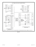
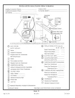
Страница 11: ...Page 11 of 18 Issue 1324 507120 01 Figure 12 Low Voltage Connections 3 Speed PSC Motor...
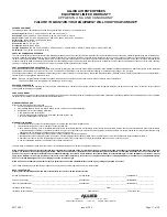
Страница 15: ...Page 15 of 18 Issue 1324 507120 01 Start Up and Performance Checklist Horizontal Configuration Figure 14...
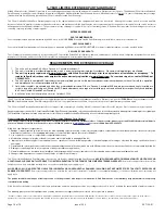
Страница 16: ...Issue 1324 507120 01 Page 16 of 18 Figure 15 Start Up and Performance Checklist Upflow Configuration...