


2.16
Arduino Shield and Pmod interfaces
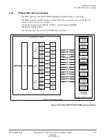
The MPS3 board supports peripheral development by providing two Arduino Shield interfaces and, as an
alternative, four Peripheral Module (Pmod) interfaces (Type 2A/3/4 support).
Overview of Shield and Pmod interfaces
The following figure shows the two Shield interfaces, and the four Pmod interfaces where the FPGA
design implements an SPI controller that drives the 12
‑
bit ADC.
MPS3 FPGA Prototyping Board
FPGA
Shield 0
IO0[15:0]
AREF0
Shield 1
SPI
controller
12-bit ADC
AD7490
ADC_CS
ADC_CLK
ADC_DIN
ADC_DOUT
IO1[15:0]
AD0[5:0]
AREF1
AD1[5:0]
Shield 0
headers
IO0[15:0]
IO1[15:0]
5V
3V3
IOREF0
IOREF1
VIN0
VIN1
Reset0
Reset1
System
registers
Level
shifter
3V3/5V
12V
Level
shifter
3V3/5V
5V
3V3
5V
3V3
Pmod 0
Pmod 1
IOREF0
Pmod 2
Pmod 3
IOREF1
IOREF1
Pmod 0
header
Pmod 1
header
Shield 1
headers
Pmod 2
header
Pmod 3
header
IOREF0
IOREF0 and
VIN0 jumper
connectors
IOREF1 and
VIN1 jumper
connectors
Figure 2-20 Shield and Pmod interfaces
The Arduino Shield and Pmod interfaces share pins on the FPGA.
2 Hardware description
2.16 Arduino Shield and Pmod interfaces
100765_0000_04_en
Copyright © 2017–2020 Arm Limited or its affiliates. All rights
reserved.
2-43
Non-Confidential