


MPS3 FPGA Prototyping Board
Kintex XCKU115 FPGA
USB 2.0
controller
Ethernet
controller
Ethernet
SMC
USB
USB
Combined Ethernet and
dual-USB connector
HDMI PHY
I
2
S I
2
C HDLCD
HDMI
Stereo audio codec
Mic In
Line In
Line Out
Audio
Stacked stereo jacks
1 2 3 4 5 6 7 8
User switches
User LEDs
QVGA CLCD and
touchscreen
I
2
C
Parallel
User
push
buttons
GPIO
GPIO
GPIO
User
microSD
eMMC
DDR4
QSPI flash
MCC
Configuration
microSD
SCC/SMBF
Configuration
Clock
generators
and 24MHz
PLLs
I
2
C
Debug USB
USB
hub
USB-serial
interface
UART
4×UART
CoreSight/Trace connectors
CoreSight
CMSIS-DAP
controller
ADC
AD0[5:0]
Shield 0
Pmod0/1
Pmod2/3
Shield 1
AD1[5:0]
IO0[15:0]
IO1[15:0]
GPIO
GPIO
ADC controller
F-JTAG ILA
F-JTAG
Hardware
reset push
buttons
On/Off Soft
reset push
buttons
PBRST
PBON
Shield and Pmod
expansion connectors
MPS3 power
supplies
FMC-HPC
Board present/
Powerup board
TLX/User I/O
System
LEDs
Push
button
LEDs
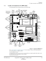
Figure 2-1 Hardware infrastructure of the MPS3 board
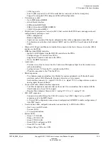
The MPS3 board contains the following components:
• One Xilinx Kintex Ultrascale XCKU115
‑
1FLVB1760C FPGA:
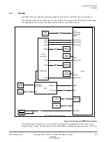
2 Hardware description
2.1 Overview of the board hardware
100765_0000_04_en
Copyright © 2017–2020 Arm Limited or its affiliates. All rights
reserved.
2-18
Non-Confidential