Installation manual for the CD72/95/15012
Page 19
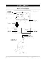
CD3008 / CD3009
KEYPAD
Display contrast
adjustment
Keypad address
setting switches
Cable entry from
top
Fixing hole
Push the side clip
to remove PCB
Cable entry from
back
Cable entry from
bottom
Fixing hole
Fixing hole
Extra screw to
secure lid
1
2
3
4
5
6
7
8
9
0
D
C
B
A
4-wire bus
connection
Buzzer volume adjustment
Figure 12. CD3008 / CD3009 keypad
CD3048 / CD3049
KEYPAD
Display contrast
adjustment
Keypad address
setting switches
Cable entry from
top
Fixing hole
Push side clip to
remove PCB
Cable entry from
back
Cable entry from
bottom
Fixing hole
Fixing hole
Extra screw to
secure lid
1
2
3
4
5
6
7
8
9
0
Four-wire bus
connection
D
C
B
A
Buzzer volume adjustment
Buzzer
2
1
4
3
OB
ON
Zones
-
+
Power connection
OFF
Jumper to cut
off Buzzer
Figure 13. CD3048 / CD3049 keypad
Remote
Connection to
connections
CD 72
CD 95/150
A
38
50
B
37
49
C
36
48
D
35
47
Содержание Advisor CD15012
Страница 1: ...142938999 1 Installation Manual Software from Version V6 0 ADVISOR CD 7212 CD95 15012 ...
Страница 4: ...Page 4 Installation manual for CD72 95 15012 ...
Страница 34: ...Page 34 Installation manual for the CD72 95 15012 ...
Страница 35: ...Installation manual for the CD72 95 15012 Page 35 ...
Страница 36: ...Page 36 Installation manual for the CD72 95 15012 ...
Страница 38: ...Page 38 Installation manual for the CD72 95 15012 ...
Страница 39: ...Installation manual for the CD72 95 15012 Page 39 ...
Страница 40: ...Page 40 Installation manual for the CD72 95 15012 ...


