background image

20

B004

3.

COMMISSIONING

3.1

Initial Preparation

Preliminary electrical system checks to ensure electrical safety must be carried
out by a competent person i.e. polarity, earth continuity, resistance to earth and
short circuit.

Filling the Heating System:

Remove the panels of the case and lower the control panel (see point 3.2. for 
further information).
Open the central heating flow and return cocks supplied with the connection 
kit.
Unscrew the cap on the automatic air release valve one full turn and leave 
open permanently.
Close all air release valves on the central heating system.
Gradually open valve(s) at the filling point (filling-loop) connection to the 
central heating system until water is heard to flow, do not open fully.
Open each air release tap starting with the lower point and close it only when
clear water, free of air, is visible.
Purge the air from the pump by unscrewing anticlockwise the pump plug and 
also manually rotate the pump shaft in the direction indicated by the pump 
label to ensure the pump is free.
Close the pump plug.
Continue filling the system until at least 1 bar registers on the pressure 
gauge.
Inspect the system for water soundness and remedy any leaks discovered.

Filling of the D.H.W. System:

Close all hot water draw-off taps.
Open the cold water inlet cock supplied with the connection kit.
Open slowly each draw-off tap and close it only when clear water, free of 
bubbles, is visible

Gas Supply:

Inspect the entire installation including the gas meter, test for soundness and 
purge, all as described in BS 6891:1988.
Open the gas cock (supplied with the connection kit) to the appliance and 
check the gas connector on the appliance for leaks.

When the installation and filling are completed turn on the central heating
system (sect. 3.4) and run it until the temperature has reached the boiler
operating temperature. The system must then be immediately flushed through.
The flushing procedure must be in line with BS 7593:1992 Code of practice for
treatment of water in domestic hot water central heating systems.
During this operation, we highly recommend the use of a central heating
flushing detergent (Fernox Superfloc or equivalent), whose function is to
dissolve any foreign matter that may be in the system.
Substances different from these could create serious problems to the
pump or other components.
The use of an inhibitor in system such as Fernox MB-1 or equivalent is strongly
recommended to prevent corrosion (sludge) damaging the boiler and system.
Failure to carry out this procedure may invalidate the appliance warranty.

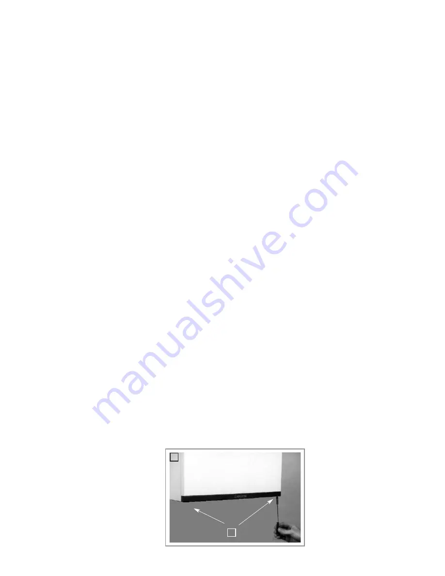
To dismantle the front part of
the casing, proceed as follows:
1. Loosen the two screws “F”

located on the bottom part 
of the boiler until the
first thread on the screws 
appears;

1

F

3.2

Removing the Casing

Содержание GENUS 27 MFFI

Страница 1: ...Installation Instructions Type C Boilers G C N 41 116 01 47 116 08 47 116 09 47 116 13 LEAVE THESE INSTRUCTIONS ADJACENT TO THE GAS METER Country of destination GB...

Страница 2: ...2 10 Room Thermostat Connection 2 11 Electrical System Diagrams 2 12 Water Circuit Diagrams 3 COMMISSIONING 3 1 Initial Preparation 3 2 Removing the Casing 3 3 Control Panel 3 4 Initial Start up 3 5...

Страница 3: ...erty You will find the data plate on the reverse of the control panel The gas with which this appliance operates is also shown on the label at the bottom of the boiler Do not install this appliance in...

Страница 4: ...sel Pre load Pressure bar 1 1 1 1 Maximum Water Content in System l 145 145 145 145 Maximum Heating Pressure bar 3 3 3 3 Nominal Pressure Natural Gas G20 G25 mbar 20 25 20 25 20 25 20 25 Liquid Gas G3...

Страница 5: ...orised Valve RFFI 10 Main Circuit Temperature Probe 11 Main Circuit Flow Switch 12 Domestic Hot Water Temperature Probe 13 Diverter Valve Microswitch 14 Filter Seat 15 Drain Valve 16 Secondary Heat Ex...

Страница 6: ...sealed appliance is installed in a room containing a bath or shower the boiler and any electrical switch or appliance control utilising mains electricity should be situated so that it cannot be touche...

Страница 7: ...A B D E C 465 99 99 132 67 65 85 155 208 30 49 F G A D E C AF C DGE GENUS 23 27 30 MFFI GENUS 27 RFFI SYSTEM In order to allow for access to the interior of the boiler for maintenance purposes the boi...

Страница 8: ...l as follows The yellow green wire should be connected to the terminal marked with the earth symbol make sure to re use the ferrule mounted on the other supply cord The blue wire should be connected t...

Страница 9: ...uitable only for sealed systems Drain Cocks These must be located in accessible positions to permit the draining of the whole system The taps must be at least 15mm nominal size and manufactured in acc...

Страница 10: ...nter and one for the summer This enables the flow rate through the appliance to be adjusted so that a sensible D H W temperature may be achieved throughout the year Domestic Water The domestic water m...

Страница 11: ...terminal facing a terminal 1200 J From an opening in the car port e g door window into dwelling 1200 K Vertically from a terminal in the same wall 1500 L Horizontally from a terminal in the same wall...

Страница 12: ...air vent intake located on the top part of the combustion chamber A A A Fig 2 8 This procedure must be done as follows 1 Remove the air vent intake you want to use in the area indicated in Fig 2 9 by...

Страница 13: ...13 B004 In Fig 2 11 below several different types of flue systems are shown For additional information regarding the flue accessories please consult the Flue Pipe Accessories manual Fig 2 11...

Страница 14: ...cated in the table 4 The exhaust pipe must extend at least 0 5 m above the ridge of the roof if it is located on a side other than that for the air intake this is not obligatory if the exhaust and air...

Страница 15: ...tat these must be connected in series as per points 1 8 above Note Only a two wire type room thermostat can be used For details on fitting the D H W probe Genus 27 RFFI only please consult the separat...

Страница 16: ...ection Q On Off L E D R On Off Switch S Interface Wire for P C B s T Relay Motorised Valve U Ignitor Relay V Gas Valve Relay W Fan Relay X Circulation Pump Relay Y Selector TCS2 Z Link for Continuous...

Страница 17: ...17 B004 Aa GENUS 23 27 30 MFFI Aa GENUS 27 RFFI SYSTEM...

Страница 18: ...18 B004 CN202 P GENUS 23 27 30 MFFI P GENUS 27 RFFI SYSTEM...

Страница 19: ...cluding Safety Pressure Switch for Primary Circuit 11 Automatic By pass 12 Microswitch for Diverter Valve 13 Sensor for Domestic Hot Water 14 Secondary Heat Exchanger 15 Domestic Water Inlet Filter 16...

Страница 20: ...r inlet cock supplied with the connection kit Open slowly each draw off tap and close it only when clear water free of bubbles is visible Gas Supply Inspect the entire installation including the gas m...

Страница 21: ...ition Lockout L E D C Selector Knob for Summer Winter Flue Analysis Modes D Low System Water Level L E D E Temperature Adjustment Knob for Domestic Hot Water F Heating System Thermometer G Safety Over...

Страница 22: ...e lines Loosen the cap on the head of the pump to eliminate any air pockets Repeat the procedure for bleeding the radiators of air Open the taps for a brief period Check the system pressure and if it...

Страница 23: ...a shutdown status With a differential manometer connected to the test socket on the combustion chamber the DP value for the air pressure switch can be taken The measured value should not be less than...

Страница 24: ...fety pressure switch on the primary circuit has not sensed a pressure of at least 1 bar within 40 seconds of the activation of the circulation pump it shuts off the boiler and lights the L E D D The s...

Страница 25: ...5 C 1013mbar mc h 3 49 Consumption 15 C 1013mbar Kg h 2 60 2 57 Gas Cock Outlet Pressure max min mbar 11 4 1 4 4 1 5 6 25 B004 The outlet pressure of the gas cock is obtained by completely loosening t...

Страница 26: ...ssembly clean the exhaust fan if needed 8 Adjustment of the flow rate of the gas flow rate for lighting partial load and full load 9 Check of the heating safety systems safety device for maximum tempe...

Страница 27: ...201 6 3 E 1 2 Towerchron FP 6 1 0 2 1 Link 1 5 4 7 9 Towerchron MP 6 1 0 2 1 Link 1 4 6 11 Towerchron 2000 HW HTG N L ON ON ACL LS522 LS722 3 4 N L Randall 922 972 3 6 E N L Link L 2 5 Randall 3020 P...

Страница 28: ...4 E 1 2 Link 2 3 6 Sunvic DHP 2201 6 3 E 1 2 Towerchron FP 6 10 2 1 Link 1 5 4 7 9 Towerchron MP 6 10 2 1 Link 1 4 6 11 Towerchron 2000 HW HTG N L ON ON ACL LS522 LS722 3 4 N L Randall 922 972 3 6 E N...

Страница 29: ...B004 NOTES...

Страница 30: ...30 B004 NOTES...

Страница 31: ...31 B004...

Страница 32: ...e f f f f e e RECANATI Manufacturer Merloni TermoSanitari SpA Italy Commercial subsidiary MTS GB LIMITED MTS Building Hughenden Avenue High Wycombe Bucks HP13 5FT Telephone 01494 755600 Fax 01494 459...

Отзывы: