Arista DCS-7504 Скачать руководство пользователя страница 9

Quick Start Guide: 7500 Series Modular Data Center Switches

5

Chapter 2

Preparation

2.1

Site Selection

The following criteria should be considered when selecting a site to install the switch:
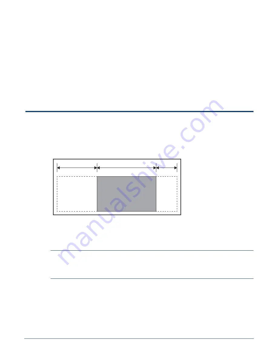
Floor Space:

Install the switch in an area that provides adequate clearance for removing front and rear

components.

Figure 2-1

displays switch clearance requirements.

Figure 2-1: Switch Component Removal Footprint

Temperature and Ventilation:

For proper ventilation, install the switch where there is ample

airflow to the front and back of the switch. The temperature should not go below 0° or exceed 40°
C.

Important!

To prevent the switch from overheating, do not operate it in an area where the ambient temperature
exceeds 40°C (104°F).

Pour empêcher l’interrupteur de surchauffe, ne pas utiliser il dans une zone où la température
ambiante est supérieure à 40° C (104° F).

Airflow Orientation:

The fans direct air from the front panel to the rear panel. Orient the front panel

toward the cool aisle.

Rack Space:

Install the switch in a 19" rack or cabinet. The switch height is 11 RU (7508 / 7508E)

or 7 RU (7504 / 7504E). The accessory kit provides mounting brackets for two-post and four-post
racks.

Linecard and 

Supervisor 

Removal 

Clearance

(Front)

60 cm (24 in)

86 cm (34 in)

32 cm (13 in)

Switch

Chassis

Fabric 

Module 

Removal 

Clearance

(Rear)

Содержание DCS-7504

Страница 1: ...Quick Start Guide 7500 Series Modular Data Center Switches DCS 7504 7504E DCS 7508 7508E Arista Networks www arista com PDOC 00015 09 ...

Страница 2: ...tworks and the Arista logo are trademarks of Arista Networks Inc in the United States and other countries Other product or service names may be trademarks or service marks of others Headquarters 5453 Great America Parkway Santa Clara CA 95054 USA 408 547 5500 www arista com Support 408 547 5502 866 476 0000 support arista com Sales 408 547 5501 866 497 0000 sales arista com ...

Страница 3: ... Attaching Mounting Brackets to the Chassis 9 3 1 2 Inserting the Switch into the Rack 10 3 2 Four Post Rack Mount 11 3 2 1 Assembling the Shelf 11 3 2 2 Inserting the Switch into the Rack 15 Chapter 4 Cabling the Switch 17 4 1 Cabling the AC Power Supply 17 4 1 1 Grounding the Switch 17 4 1 2 Connecting Power Cables to an AC Power Supply 18 4 2 Connecting Supervisor Cables 20 4 3 Connecting Line ...

Страница 4: ...rts List 29 B 1 Two Post Rack Mount Parts 29 B 2 Four Post Rack Mount Parts 30 B 3 Parts Used in All Rack Mount Configurations 30 B 3 1 Cables 30 B 3 2 Equipment 31 B 3 3 Rack Mount Alternate Parts 31 Appendix C Front Panel 33 Appendix D Rear Panel 37 Appendix E Line Cards 41 ...

Страница 5: ...t of the shipment is damaged the carrier may need to inspect them If the boxes were not damaged in transit unpack them carefully Ensure that you do not discard any accessories that may be packaged in the same box as the main unit Inspect the packing list and confirm that you received all listed items Compare the packing list with your purchase order Appendix B provides a list of components include...

Страница 6: ...sion admissible par EN IEC 60825 CSA E60825 1 et Code des règlements fédéraux 21 CFR 1040 ne soit pas dépassée après avoir installé l émetteur récepteur de laser Ne pas installer des appareils à laser dont la cote de classe est supérieure à 1 Voir toutes les consignes de sécurité qui ont accompagné l émetteur récepteur avant l installation Seuls appareils laser de classe 1 certifiés pour une utili...

Страница 7: ... circuits Ambient Temperature Storage Temperature Relative Humidity Altitude 0 to 40 C 32 to 104 F 40 to 70 C 40 to 158 F 5 to 90 0 to 3 000 meters 0 to 10 000 feet 0 to 40 C 32 to 104 F 40 to 70 C 40 to 158 F 5 to 90 0 to 3 000 meters 0 to 10 000 feet Cooling 6600 W maximum 3300 W maximum Table 1 2 7500 Series Power Specifications Module Type Part Number Power Draw Typical Maximum Supervisor Modu...

Страница 8: ...4 Quick Start Guide 7500 Series Modular Data Center Switches Specifications Chapter 1 Overview ...

Страница 9: ...ure should not go below 0 or exceed 40 C Important To prevent the switch from overheating do not operate it in an area where the ambient temperature exceeds 40 C 104 F Pour empêcher l interrupteur de surchauffe ne pas utiliser il dans une zone où la température ambiante est supérieure à 40 C 104 F Airflow Orientation The fans direct air from the front panel to the rear panel Orient the front panel...

Страница 10: ...ite where liquids or objects cannot fall onto the equipment and foreign objects are not drawn into the ventilation holes Verify these guidelines are met Clearance areas to the front and rear panels allow for unrestricted cabling All front and rear panel indicators can be easily read AC power cords can reach from the AC power outlet to the connectors on the front panel Important Disconnecting power...

Страница 11: ...ssemble or disassemble equipment only in a static free work area Use a conductive work surface such as an anti static mat to dissipate static charge Wear a conductive wrist strap to dissipate static charge accumulation Minimize handling of assemblies and components Keep replacement parts in their original static free packaging Remove all plastic foam vinyl paper and other static generating materia...

Страница 12: ...8 Quick Start Guide 7500 Series Modular Data Center Switches Electrostatic Discharge ESD Precautions Chapter 2 Preparation ...

Страница 13: ...ceed to Chapter 4 3 1 Two Post Rack Mount To mount the switch to a two post rack assemble mounting brackets to the middle of the chassis then attach the brackets to the rack The switch does not support a front or rear mount into a two post rack The accessory kit includes the following two post mounting parts 2 center mount brackets 20 M4x8 panhead Phillips screws Figure B 2 on page 30 displays the...

Страница 14: ...lly to avoid damaging any components Step 2 Lift the chassis into the rack Position the flanges against the rack posts Figure 3 2 Figure 3 2 Lifting the Switch Chassis into the Two Post Rack Step 3 Select mounting screws that fit your equipment rack A minimum of four screws is required on each side of the chassis The accessory kit provides screws that fit many common equipment racks When installin...

Страница 15: ...owing four post mounting parts 2 front brackets 4 shelf supports 2 back brackets not needed for racks with threaded holes left shelf right shelf Figure B 1 on page 29 displays the four post mounting parts 3 2 1 Assembling the Shelf Step 1 Attach the front bracket and shelf support to the left front rack post as shown in Figure 3 4 on page 12 An up arrow is printed on the shelf support to indicate ...

Страница 16: ...inted on the shelf support to indicate its proper orientation Unthreaded rack holes Attach the parts as displayed in Figure 3 5 left Threaded rack holes Attach the shelf support to the post with screws that thread into the rack post The back bracket is not required on threaded racks Figure 3 5 Left Rear Post Assembly and Shelf Support Orientation Four Post Rack Mount Step 4 Adjust the left shelf b...

Страница 17: ...e shelf supports installed on the left front and left rear rack posts step 1 and step 3 Align the holes Inset A and hook Inset B with the stubs on the brackets Lower the shelf such that the bracket stubs are inserted into the shelf holes and hook Figure 3 7 on page 14 Press down firmly on the shelf to ensure it is seated securely on the rack posts Left Shelf Rear Rack Post Front Rack Post ...

Страница 18: ...elf Step 6 Install the right shelf on the right front and right rear rack posts by repeating step 4 and step 5 to obtain the rack configuration shown in Figure 3 8 Figure 3 8 Both Switch Shelves Installed Inset B Inset A Inset B Inset A Inset A Inset A Front Left Rack Post Rear Left Rack Post Front Rack Posts Rear Rack Posts Right Shelf Left Shelf ...

Страница 19: ...ift Figure 3 9 If modules are inserted in the chassis use the lift carefully to avoid damaging any components Step 2 Lift the chassis into the rack Figure 3 9 Lifting the Switch Chassis Step 3 Secure the chassis by tightening the four thumbscrews on the front flanges into the rack posts Figure 3 10 Figure 3 10 Inserting the Switch onto the Rack Shelf After completing the Four Post Installation pro...

Страница 20: ...16 Quick Start Guide 7500 Series Modular Data Center Switches Four Post Rack Mount Chapter 3 Rack Mounting the Switch ...

Страница 21: ... 4 1 Grounding Pad and ESD Grounding Port Sockets After the switch is grounded ESD wrist straps can be grounded by connecting them to one of the ESD grounding ports located between the power input sockets Figure 4 1 or the rear panel Figure 4 2 on page 18 depicts the location on the 7504 Receptacles are available in similar locations on other switch models INPUT PS 4 200 240V AC 50 60Hz 16A INPUT ...

Страница 22: ... four power supplies protects against up to two failed power supplies and can provide grid level redundancy Energizing any power supply causes all power supply fans to function Figure 4 3 displays the power input sockets Appendix C displays the front panel location of the sockets Figure 4 3 Power Input Sockets Important Read all installation instructions before connecting the system to the power s...

Страница 23: ...scribed in this guide Appendix C displays the front panel location of the power input sockets and supervisor modules Appendix D displays the rear panel location of power supplies and fan modules The switch uses power cables that comply with IEC 320 and have a C19 plug The accessory kit provides four IEC 320 C19 to C20 power cables each two meters long To insert a power cable Step 1 Lift the retain...

Страница 24: ...8E 7504E switches Figure 4 5 Supervisor Ports 7508E 7504E Switches Console Serial Port ConnecttoaPCwithRJ 45toDB 9serialadaptercable Defaultswitchsettings include 9600 baud No flow control 1 stop bit No parity bits 8 data bits Ethernet management port Connect to 10 100 1000 management network with RJ 45 cable USB Port May be used for software or configuration updates POWER SUPPLIES 1 2 3 4 FABRIC ...

Страница 25: ...e card module ports Figure 4 6 Figure 4 6 SFP or SFP ports Connect cables as required to line card module ports or fixed MPO ports Supervisor and line card module ejectors on the front of the chassis assist with cable management Caution Excessive bending can damage interface cables especially optical cables Flexion excessive peut endommager les câbles d interface notamment des câbles optiques 4 42...

Страница 26: ...22 Quick Start Guide 7500 Series Modular Data Center Switches Connecting Line Card Modules and Cables Chapter 4 Cabling the Switch ...

Страница 27: ...default route to a network gateway Step 1 Provide power to the switch Section 4 1 2 Step 2 Connect the console port to a PC Section 4 2 As the switch boots without a startup config file it displays this message through the console The device is in Zero Touch Provisioning mode and is attempting to download the startup config from a remote system The device will not be fully functional until either ...

Страница 28: ... address 192 0 2 8 24 in this example to an Ethernet management port localhost config interface management 1 1 localhost config if Ma1 1 ip address 192 0 2 8 24 Step 10 Save the configuration by typing write memory or copy running config startup config localhost copy running config startup config When the management port IP address is configured use this command to access the switch from a host us...

Страница 29: ...n Ethernet management port and a USB port Supervisor activity is reported by LEDs in the upper left quadrant The Status Summary Screen in the center reports status for other components Figure A 1 depicts the 7508 7504 Supervisor Module Figure A 1 Supervisor Module 7508 7504 Supervisor Activity Status The Status and Active LEDs report supervisor activity status Table A 1 interprets the states of bo...

Страница 30: ...rvisor Activity Status LEDs The Status and Active LEDs are located on the left side of the Supervisor Module Table A 3 interprets the states of these two LEDs Status LED Red Module failed Active LED Off Supervisor is not active Active LED Green Supervisor is active and controlling the switch Table A 2 Supervisor Status Summary Screen LED States 7508 7504 LED State Status Gray Module not present or...

Страница 31: ...of the DCS 7500E 36Q LC line card Figure A 3 line card Status LED The line card Status LED is in the top left corner of the DC 7548S LC line card Table A 5 interprets the states of the Status LED The line card provides LEDs for each port module socket Figure A 3 left displays SFP module LEDs Each LED corresponds to a module Table A 4 Component Activity LED States 7508E 7504E LED Name LED State Mod...

Страница 32: ...E and DCS 7504E Appendix D displays the position of these LEDs on the rear of each switch Figure A 4 displays Fan Status and Fabric Status LEDs on the DCS 7508 and DCS 7504 switches Figure A 4 Fan Status and Fabric Status LEDs Table A 7 interprets the states of the Fan and Fabric Status LED Table A 6 line card Port LED States LED State Status Off Port link is down Green Port link is up Yellow Port...

Страница 33: ...the switch This appendix lists the installation parts contained in the switch accessory kit B 1 Two Post Rack Mount Parts Figure B 1 Two Post Rack Mount Parts Table B 1 Two Post Rack Mount Parts Quantity Description 2 Center mount brackets 20 M4x8 panhead Phillips screws Center mount brackets 2 7508 only M4x8 panhead Phillips screws 20 Center mount brackets 2 7504 only ...

Страница 34: ...ont brackets 4 Shelf supports 2 Back brackets 1 Left shelf 1 Right shelf 10 M6X16 panhead Phillips screws 4 M6 Cage Hex Nuts 2 M6 Cage Nut Square Hole Racks Front Brackets 2 7508 only Back Brackets 2 Left Shelf 1 Right Shelf 1 Shelf Supports 4 M6x16 Panhead Phillips Screws 10 M6 Nuts 4 M6 Cage Nuts 2 Front Brackets 2 7504 only Table B 3 Cables Provided in Accessory Kit Quantity Description 4 power...

Страница 35: ...ࡣࠊ ULVWD ࡢ〇ရ ࡢࡳ ࡋ ࡃࡔࡉ ࠋ B 3 2 Equipment B 3 3 Rack Mount Alternate Parts These parts are supplied for threaded racks that do not use M6 screws Table B 4 Installation Equipment Provided in Accessory Kit Quantity Description 1 Adjustable Wrench Table B 5 Threaded Rack Post Parts Quantity Description 5 M5 hex nuts 11 M5X16 panhead Phillips screws 5 12 24 hex nuts 11 12 24X5 8 panhead Phillips screws ...

Страница 36: ...32 Quick Start Guide 7500 Series Modular Data Center Switches Parts Used in All Rack Mount Configurations Appendix B Parts List ...

Страница 37: ...ered by this guide DCS 7508 Front Panel fully populated POWER SUPPLIES 1 2 3 4 FABRIC MODULES 1 2 3 4 5 6 FAN MODULES 1 2 3 4 5 6 LINECARDS 3 4 5 6 7 8 9 10 Status Summary POWER SUPPLIES 1 2 3 4 FABRIC MODULES 1 2 3 4 5 6 FAN MODULES 1 2 3 4 5 6 LINECARDS 3 4 5 6 7 8 9 10 Status Summary Linecard Modules Supervisor Modules Power Input Sockets ...

Страница 38: ...33 44 48 46 42 40 38 36 34 11 15 13 9 7 5 3 1 12 16 14 10 8 6 4 2 27 31 29 25 23 21 19 17 28 32 30 26 24 22 20 18 43 47 45 41 39 37 35 33 44 48 46 42 40 38 36 34 11 15 13 9 7 5 3 1 12 16 14 10 8 6 4 2 27 31 29 25 23 21 19 17 28 32 30 26 24 22 20 18 43 47 45 41 39 37 35 33 44 48 46 42 40 38 36 34 11 15 13 9 7 5 3 1 12 16 14 10 8 6 4 2 27 31 29 25 23 21 19 17 28 32 30 26 24 22 20 18 43 47 45 41 39 3...

Страница 39: ...11 15 13 9 7 5 3 1 12 16 14 10 8 6 4 2 27 31 29 25 23 21 19 17 28 32 30 26 24 22 20 18 43 47 45 41 39 37 35 33 44 48 46 42 40 38 36 34 11 15 13 9 7 5 3 1 12 16 14 10 8 6 4 2 27 31 29 25 23 21 19 17 28 32 30 26 24 22 20 18 43 47 45 41 39 37 35 33 44 48 46 42 40 38 36 34 11 15 13 9 7 5 3 1 12 16 14 10 8 6 4 2 27 31 29 25 23 21 19 17 28 32 30 26 24 22 20 18 43 47 45 41 39 37 35 33 44 48 46 42 40 38 3...

Страница 40: ...36 Quick Start Guide 7500 Series Modular Data Center Switches Appendix C Front Panel ...

Страница 41: ...TUS SERIAL MODEL REMOVE FAN TO ACCESS FABRIC CARD FAN BOTTOM FAN STATUS FABRIC STATUS SERIAL MODEL REMOVE FAN TO ACCESS FABRIC CARD FAN BOTTOM FAN STATUS FABRIC STATUS SERIAL MODEL REMOVE FAN TO ACCESS FABRIC CARD FAN BOTTOM FAN STATUS FABRIC STATUS SERIAL MODEL REMOVE FAN TO ACCESS FABRIC CARD FAN BOTTOM FAN STATUS FABRIC STATUS SERIAL MODEL REMOVE FAN TO ACCESS FABRIC CARD FAN BOTTOM Ø 10 00 mm ...

Страница 42: ...IC 4 FABRIC 5 FABRIC 6 FABRIC MODULE FM BOTTOM ASSEMBLY MODEL 7508 FAB2 SERIAL SYSTEM WILL OVERHEAT REPLACE MODULE 1 min TOP ROTATE HANDLES 90o TO STOPS BEFORE PULLING OUT MODULE FABRIC MODULE FM BOTTOM ASSEMBLY MODEL 7508 FAB2 SERIAL SYSTEM WILL OVERHEAT REPLACE MODULE 1 min TOP ROTATE HANDLES 90o TO STOPS BEFORE PULLING OUT MODULE FABRIC MODULE FM BOTTOM ASSEMBLY MODEL 7508 FAB2 SERIAL SYSTEM WI...

Страница 43: ...AC OK FAULT PWR 75 2900AC OK FAULT PWR 75 2900AC OK FAULT PWR 75 2900AC FAN FC STATUS SERIAL ASSEMBLY FM 7504 FAN FC STATUS SERIAL ASSEMBLY FM 7504 FAN FC STATUS SERIAL ASSEMBLY FM 7504 FAN FC STATUS SERIAL ASSEMBLY FM 7504 FAN FC STATUS SERIAL ASSEMBLY FM 7504 FAN FC STATUS SERIAL ASSEMBLY FM 7504 FM1 PS1 FM3 PS2 FM2 FM4 PS3 FM5 PS4 FM6 Fan Fabric Modules Fan and Fabric Status LEDs Power Supplies...

Страница 44: ...40 Quick Start Guide 7500 Series Modular Data Center Switches Appendix D Rear Panel ...

Страница 45: ...ed by modular switches covered by this guide DCS 7548S LC DCS 7500E 36Q LC DCS 7500E 72S LC 10G Port LEDs Status LED 40G Port LEDs 10G Port LEDs Status LED 11 15 13 9 7 5 3 1 12 16 14 10 8 6 4 2 27 31 29 25 23 21 19 17 28 32 30 26 24 22 20 18 43 47 45 41 39 37 35 33 44 48 46 42 40 38 36 34 10G Port LEDs MXP Port LEDs Status LED ...

Страница 46: ...7500E 12CQ LC DCS 7500E 6CFPX LC 11 15 13 9 7 5 3 1 12 16 14 10 8 6 4 2 27 31 29 25 23 21 19 17 28 32 30 26 24 22 20 18 43 47 45 41 39 37 35 33 44 48 46 42 40 38 36 34 10G Port LEDs Status LED MXP Port LEDs Status LED CFP2 Port LEDs Status LED 40 100G Port LEDs Status LED 7500 6CFPX LC 1 2 3 4 5 6 STATUS Coherent 100G 100G Ports Status LED ...

Отзывы: