Chapter 2: Preparation
7010 Series 1 RU Quick Start Guide
PDOC-00061-02
5
Chapter 2 Preparation
2.1
Site Selection
The following criteria should be considered when selecting a site to install the switch:
•
Temperature and Ventilation:
For proper ventilation, install the switch where there is ample airflow
to the front and back of the switch. The ambient temperature should not go below 0° or exceed 40° C.
Important!
To prevent the switch from overheating, do not operate it in an area where the ambient temperature
exceeds 40°C (104°F).
•
Airflow Orientation:
Determine front and rear aisle temperatures and verify that fan is inserted
appropriately for switch installation.
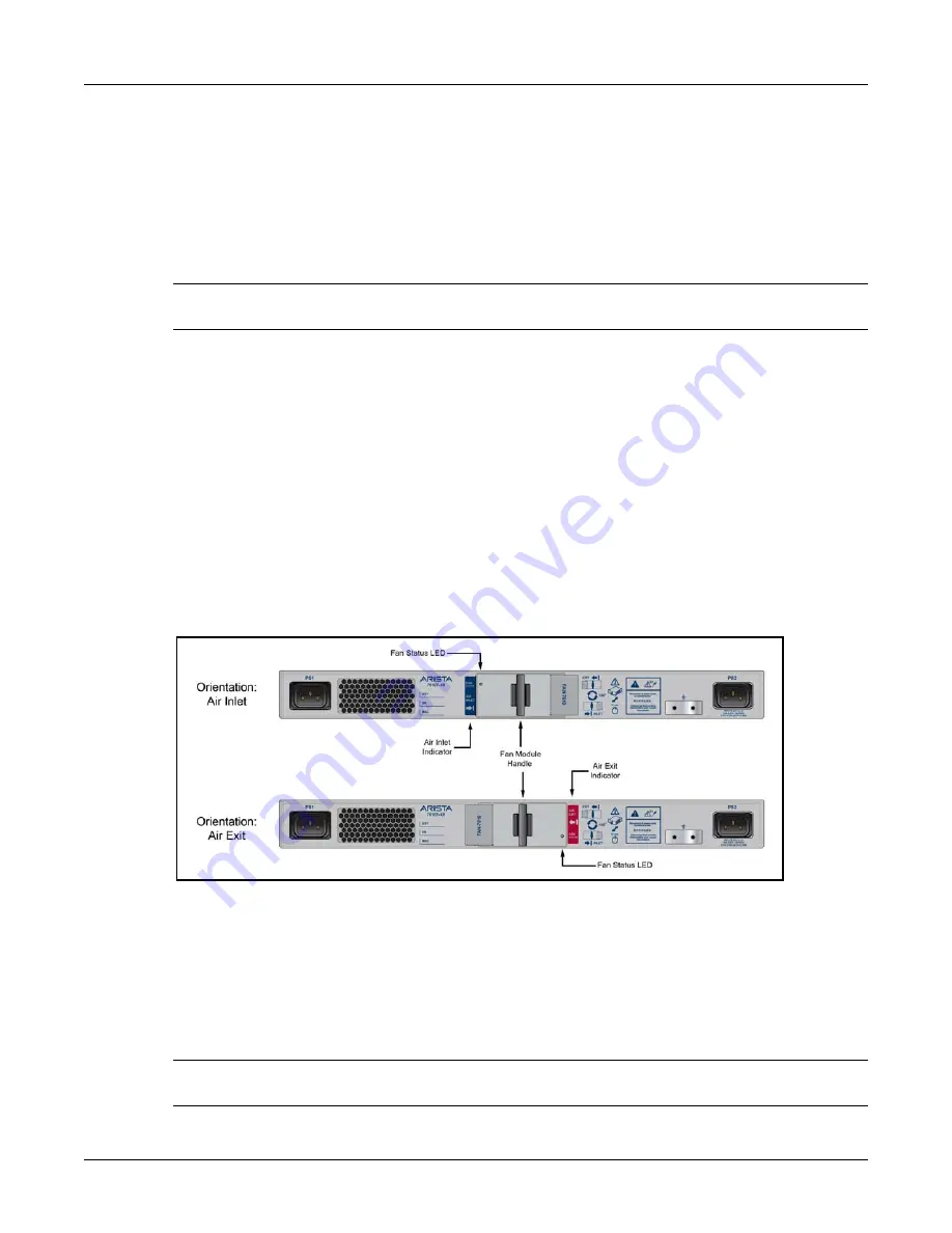
The fan orientation determines the airflow direction through the switch. The fan orientation is
changed by removing the fan from the switch, rotating it 180°, then re-inserting it into the switch.
The color of the visible label indicates the airflow direction.
Figure 1
displays the rear panels of two
switches with different fan orientations:
—
Blue Label visible
: Air Inlet direction.
—
Red Label visible
: Air Exit direction.
Orient the fan direction to assure the air inlet always faces the cool aisle:
—
Air Exit label visible:
orient front panel toward cool aisle.
—
Air Inlet label visible :
orient front panel toward hot aisle.
Appendix A
describes the process of changing the fan orientation.
•
Rack Space:
Install the switch in a 19" rack (cabinet) or place it on a flat surface. The switch height
is 1 RU. The accessory kit provides brackets for rack mounting and rubber pads for a flat surface
placement.
•
Power Requirements:
Refer to
Table 1
.
Two circuits provide redundancy protection.
Chapter 4
describes power cable requirements.
Important!
The power input plug-socket combination must be accessible at all times; it provides the primary
method of disconnecting power from the system.
Figure 1: Rear Panels with Contrasting Fan Module Orientation


