background image

Appendix C: Parts List

7010 Series 1 RU Quick Start Guide

PDOC-00061-02

17

Appendix C   Parts List

Each switch provides an accessory kit that contains parts that are required to install the switch. This 

appendix lists the installation parts contained in the switch accessory kit.

C.1

Installation Parts

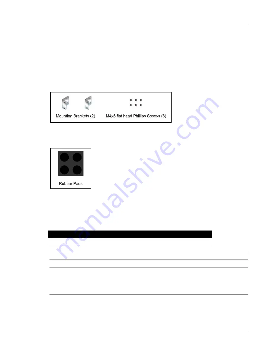
Rack mount and flat surface placement parts are provided in the accessory kit.

C.1.1

Rack Mount Parts

C.1.2

Flat Surface Placement Parts

C.2

Cables

Power cables are only provided for the DCS-7010T-48 switch.

Warning!

All provided power cables are for use only with Arista products.

警告

すべての電源コードは提供する製品で使用するためだけを目的としている。

電源コードの他の製品での使用の禁止

Arista が提供するすべての電源コードは、Arista の製品でのみ使用してください。

Figure 14: Rack Mount Parts

Figure 15: Flat Surface Placement Parts

Table 5:  Switch Cables (AC Power Supply)

Quantity

Description

2

Power cables: IEC-320/C13-C14, 10 A, 250 V

Содержание DCS-7010T-48

Страница 1: ...Quick Start Guide 7010 Series 1 RU Data Center Switches DCS 7010T 48 DCS 7010T 48 DC Arista Networks www arista com PDOC 00061 02 ...

Страница 2: ... trademarks of Arista Networks Inc in the United States and other countries Other product or service names may be trademarks or service marks of others Headquarters 5453 Great America Parkway Santa Clara CA 95054 USA 408 547 5500 www arista com Support 408 547 5502 866 476 0000 support arista com Sales 408 547 5501 866 497 0000 sales arista com ...

Страница 3: ...listed in Section 2 2 Step 3 Attach the mounting brackets and install the switch in an equipment rack Chapter 3 Step 4 Connect the switch to the power source and network devices Chapter 4 Step 5 Configure the switch Chapter 6 Important Class 1 Laser Product This product has provisions to install Class 1 laser transceivers which provide optical coupling to the communication network Once a Class 1 l...

Страница 4: ...rity Advisories and Field Notices Phone 866 476 0000 or 408 547 5502 Important No user serviceable parts inside Refer all servicing to qualified service personnel 1 6 Specifications Table 1 lists the specifications of Arista Data Center switches covered by this guide Table 1 Switch Specifications Size W x H x D all switches 44 5 x 4 4 x 25 4 cm 19 x 1 75 x 10 inches Weight all switches 4 3 kg 9 5 ...

Страница 5: ...to the switch The color of the visible label indicates the airflow direction Figure 1 displays the rear panels of two switches with different fan orientations Blue Label visible Air Inlet direction Red Label visible Air Exit direction Orient the fan direction to assure the air inlet always faces the cool aisle Air Exit label visible orient front panel toward cool aisle Air Inlet label visible orie...

Страница 6: ...ack Mount Two Post or Four Post Screws or rack mounting nuts and bolts 2 Phillips Screwdriver Flat Surface Placement No additional equipment required Accessory kit does not include screws for attaching the switch to the equipment rack When installing the switch into an equipment rack with unthreaded post holes nuts are also required to secure the switch to the rack posts 2 3 Electrostatic Discharg...

Страница 7: ... attaches to only two posts of a rack the installation process for each type of rack is identical When rack mounting a switch that was previously prepared for a surface placement remove the rubber pads from the bottom of the switch To mount the switch in a rack assemble the mounting brackets to the chassis then attach the brackets to the rack posts Rack mount accessory kits include the following p...

Страница 8: ...ent The switch is prepared for flat surface placement by attaching four rubber pads on the bottom of the chassis to prevent the switch from sliding on the table and to protect the surface of the table The installation kit provides the following four post mounting parts Four rubber switch pads To prepare the switch for placement on a flat surface peel the four rubber pads from the master sheet and ...

Страница 9: ...ndant Power Supply Configuration Connect power to both power supplies Power down the Switch Remove all power cords and wires from the power supplies Important This equipment must be grounded Never defeat the ground conductor Important This unit requires overcurrent protection 4 1 Cabling the AC Power Supply DCS 7010T 48 4 1 1 Grounding the Switch After mounting the switch into the rack connect the...

Страница 10: ...al Lug ring or spade 14 16 AWG 6 M3 5 screw Overcurrent protection 20 A Important Wire size must comply with local and national requirements and electrical codes Use only copper wire DC power supplies require 40 72 VDC absolute voltage and draws 1 8 1 0 A The power supply has reverse polarity protection Important Before performing any installation actions ensure power is removed from DC circuits b...

Страница 11: ...witches covered by this guide Connect the front panel ports as follows Console Serial Port Connect to a PC with a serial adapter cable The switch uses the following default settings 9600 baud No flow control 1 stop bit No parity bits 8 data bits Ethernet Management Port Connect to 100 1000 management network with RJ 45 Ethernet cable USB Port The USB port may be used for software or configuration ...

Страница 12: ...ither a valid startup config is downloaded from a remote system or Zero Touch Provisioning is cancelled To cancel Zero Touch Provisioning login as admin and type zerotouch cancel at the CLI localhost login Step 3 Log into the switch by typing admin at the login prompt localhost login admin Step 4 Cancel ZTP mode by typing zerotouch cancel IMPORTANT This step initiates a switch reboot localhost zer...

Страница 13: ...through the switch Figure 10 displays the rear panel with the fan module removed from the switch The fan module when inserted covers one of the two airflow labels the visible label specifies the current airflow direction The switch shuts down when the fan module is removed for more than one minute To change the airflow direction change the fan module orientation Step 1 While squeezing the fan modu...

Страница 14: ...lays the DCS 7010T 48 front panel LEDs Figure 11 System Status Indicators Table 2 Switch Indicators LED States LED Name LED State Device Status System Status Blinking Green System powering up Green All power supplies and fans are operating normally Blue The locator function is active Red Is in a failed state Fan Status Green Fan is operating normally Red Fan is not inserted or has failed Power Sup...

Страница 15: ...D location on the DCS 7010T 48 switch Appendix D displays the port LED locations of all switches covered by this guide Table 3 provides status conditions that correspond to port LED states Port LED behavior for SFP and 100 1000 Base T ports is consistent Figure 12 Port LEDs Table 3 Port LED States LED State Status Off Port link is down Green Port link is up Yellow Port is software disabled Flashin...

Страница 16: ...as displayed in Figure 13 Appendix E displays the Fan Status LED locations of all switches covered by this guide Table 4 provides status conditions that correspond to fan status LED states Figure 13 Fan Status LED Table 4 Fan Status LED States LED State Status Off The fan module is inserted but not receiving power it may not be properly seated Green The fan is operating normally Red The fan has fa...

Страница 17: ...rface placement parts are provided in the accessory kit C 1 1 Rack Mount Parts C 1 2 Flat Surface Placement Parts C 2 Cables Power cables are only provided for the DCS 7010T 48 switch Warning All provided power cables are for use only with Arista products 警告 すべての電源コードは提供する製品で使用するためだけを目的としている 電源コードの他の製品での使用の禁止 Arista が提供するすべての電源コードは Arista の製品でのみ使用してください Figure 14 Rack Mount Parts Figure 15 Flat Su...

Страница 18: ... 2014 Appendix D Front Panel Appendix D Front Panel This appendix displays the front panel of all switches covered by this guide DCS 7010T 48 DCS 7010T 48 DC Figure 16 DCS 7010T 48 Front Panel Figure 17 DCS 7010T 48 DC Front Panel ...

Страница 19: ... RU Quick Start Guide PDOC 00061 02 19 Appendix E Rear Panel This appendix displays the rear panel of all switches covered by this guide DCS 7010T 48 DCS 7010T 48 DC Figure 18 DCS 7010T 48 Rear Panel Figure 19 DCS 7010T 48 DC Rear Panel ...

Страница 20: ...20 Arista Networks Copyright 2014 Appendix E Rear Panel ...

Отзывы: