


GB - 4
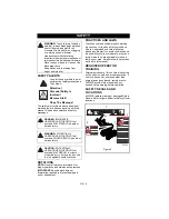
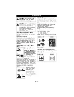
SAFETY ALERTS
Look for these symbols to point
out important safety precautions.
They mean:
Attention!
Personal Safety Is
Involved!
Become Alert!
Obey The Message!
The safety alert symbols above and signal
words below are used on decals and in this
manual. Read and understand all safety
messages.
NOTATIONS
NOTE: General reference information for
proper operation and maintenance practices.
IMPORTANT: Specific procedures or
information required to prevent damage to
unit or attachment.
PRACTICES AND LAWS
Practice usual and customary safe working
precautions, for the benefit of yourself and
others. Understand and follow all safety
messages. Be alert to unsafe conditions and
the possibility of minor, moderate, or serious
injury or death. Learn applicable rules and
laws in your area. Always follow the practices
set forth in this manual.
REQUIRED OPERATOR
TRAINING
Original purchaser of this unit was instructed
by the seller on safe and proper operation. If
unit is to be used by someone other than
original purchaser; loaned, rented or sold,
ALWAYS provide this manual and any
needed safety training before operation.
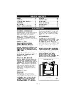
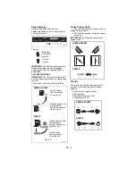
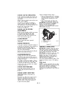
SAFETY DECALS AND
LOCATIONS
ALWAYS replace missing or damaged Safety
Decals. Refer to figure below for Safety Decal
locations.
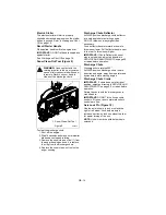
SAFETY
WARNING: To avoid injury to hands
and feet, always disengage clutches,
shut off engine, and wait for all
movement to stop before unclogging
or working on snow thrower.
Hand contact with the rotating
impeller is the most common cause of
injury associated with snow throwers.
Never use your hand to clean out the
discharge chute.
Keep hands and feet away from
auger and impeller.
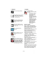
DANGER: IMMINENTLY
HAZARDOUS SITUATION! If not
avoided, WILL RESULT in death or
serious injury.
WARNING: POTENTIALLY
HAZARDOUS SITUATION! If not
avoided, COULD RESULT in death or
serious injury.
CAUTION: POTENTIALLY
HAZARDOUS SITUATION! If not
avoided, MAY RESULT in minor or
moderate injury. It may also be used
to alert against unsafe practices.
B
08000127A
1
3
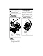
Figure 2
OS8015
2
Содержание 920006
Страница 32: ...GB 32...
Страница 35: ...Ariens Company 655 West Ryan Street Brillion WI 54110 1072 920 756 2141 www ariens com...


