


GB - 17
9. Repeat steps 7 and 8 until engine starts.
(If engine does not start, refer to
TROUBLESHOOTING on page 30.)
10. Adjust choke as needed.
11. Set throttle to Part Throttle or Slow
position for adaptation to outside
temperature or travel. Set throttle to Fast
position for normal operation.
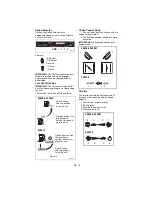
Electric Start (120V)
1. Connect extension cord to starter.
IMPORTANT: Prevent damage to unit. Know
voltage of your starter and only use matching
outlets.
2. Plug extension cord into 120V 3-wire,
grounded outlet.
IMPORTANT: Use only Ariens extension cord
(P/N 02483100) or an equilavent cord that is
rated for a minimum of 13 amps, grounded,
UL listed, CSA certified and labeled as
suitable for outdoor use.
3. Turn discharge chute straight ahead.
4. Make sure that the traction clutch and
attachment drive clutch levers are fully
disengaged.
5. Push Primer Bulb 2 or 3 times for cold
engine.
NOTE: When temperature is below -15° F
(-26° C) additional priming may be needed.
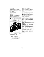
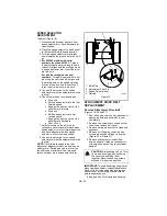
6. Insert key into ignition switch and push
into RUN position. DO NOT twist key
after it is inserted.
7. If engine is cold, apply choke. A warm
engine requires less choking than a cold
engine. See Engine Manual for detailed
instructions.
8. Set throttle to proper starting position
9. Press starter button on engine until
engine starts.
IMPORTANT: DO NOT operate starter more
than 15 seconds per minute, as overheating
and damage can occur. (If engine does not
start, refer to TROUBLESHOOTING on
page 30.)
10. Adjust choke as needed.
11. Disconnect power cord from outlet, then
starter.
12. Set throttle to Part Throttle or Slow
position for adaptation to outside
temperature or travel. Set throttle to Fast
position for normal operation.
Shut Off
1. Release Traction Drive Clutch Lever and
allow unit to come to a complete stop.
2. Run Impeller a few minutes after use to
prevent freeze-up of Impeller.
3. Release Attachment Clutch Lever and
wait for all moving parts to come to a
complete stop.
4. Move Throttle to the “Stop” position
5. Remove key.
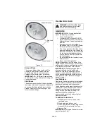
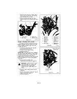
SNOW REMOVAL
IMPORTANT: Allow unit and engine to adjust
to the outdoor temperature before clearing
snow.
NOTE: Attachment clutch should be engaged
before wheel drive clutch when throwing
snow.
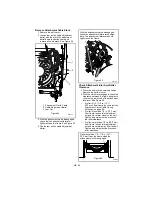
1. Select Speed Control position and
direction.
2. Engage Attachment Clutch - Right Hand
Lever.
3. Engage Traction Drive Clutch - Left
Hand Lever.
IMPORTANT: DO NOT overload unit capacity
by attempting to clear snow at too fast a rate.
Use slow speed to clear deep or hard packed
snow.
Tips for Operation
Snow is best removed as soon as possible
after snow fall.
To clear an area, run unit in an overlapping
series of paths. For large areas, start in the
middle and throw snow to each side, so snow
is not cleared more than once.
ALWAYS direct snow away from area to be
cleared and with direction of the wind.
TRAVELING
To travel from one work area to another:
1. Set Throttle to Slow or Part-Throttle
position.
2. Press down on handlebars enough to
raise front of unit slightly off surface.
3. Engage wheel drive clutch without
engaging attachment drive clutch.
TRANSPORT
ALWAYS shut off engine, remove key, and
close fuel shut-off valve when transporting
unit on a truck or trailer.
Use extra care when loading or unloading
unit onto trailer or truck.
Secure unit chassis to transport vehicle.
NEVER secure from rods or linkages that
could be damaged.
DO NOT transport machine while engine is
running.
Содержание 920006
Страница 32: ...GB 32...
Страница 35: ...Ariens Company 655 West Ryan Street Brillion WI 54110 1072 920 756 2141 www ariens com...


