background image

GB - 15

5. Set throttle to proper starting position.

6. Insert key into ignition switch and push into RUN 

position. DO NOT twist key after it is inserted.

7. Grasp starter handle and pull rope out slowly until 

it pulls harder. Let rope rewind slowly.

8. Pull rope with a rapid continuous full arm stroke. 

Let rope rewind slowly. 

IMPORTANT: DO NOT let Starter Handle snap against 
Starter. 

9. Repeat steps 7 and 8 until engine starts. (If 

engine does not start, refer to 
TROUBLESHOOTING on page 25.)

10. Adjust choke as needed.

11. Set throttle to Part Throttle or Slow position for 

adaptation to outside temperature or travel. Set 
throttle to Fast position for normal operation.

Electric Start (120V)

1. Connect extension cord to starter.

IMPORTANT: Prevent damage to unit. Know voltage of 
your starter and only use matching outlets.

2. Plug extension into 120V 3-wire, grounded outlet.

3. Turn discharge chute straight ahead.

4. Make sure that the traction clutch and attachment 

drive clutch levers are fully disengaged.

5. Push Primer Bulb 2 or 3 times for cold engine.

NOTE: When temperature is below -15° F (-26° C) 
additional priming may be needed.

6. Insert key into ignition switch on engine and push 

into "Run" position. DO NOT twist key after it is 
inserted.

7. If engine is cold, apply choke. A warm engine 

requires less choking than a cold engine. See 
Engine Manual for detailed instructions. 

8. Set throttle to proper starting position.

9. Press starter button on engine until engine starts.

IMPORTANT: DO NOT operate starter more than 15 
seconds per minute, as overheating and damage can 
occur. (If engine does not start, refer to 
TROUBLESHOOTING on page 25.)

10. Adjust choke as needed.

11. Disconnect power cord from outlet, then starter.

12. Set throttle to Part Throttle or Slow position for 

travel or adaptation to outside temperature. Set 
throttle to Fast position for normal operation.

Shut Off

1. Release Traction Drive Clutch Lever and allow 

unit to come to a complete stop.

2. Run Impeller a few minutes after use to prevent 

freeze-up of Impeller.

3. Release Attachment Clutch Lever and wait for all 

moving parts to come to a complete stop.

4. Move Throttle to the “Stop” position.

5. Remove key.

SNOW REMOVAL

IMPORTANT: Allow unit and engine to adjust to the 
outdoor temperature before clearing snow.

NOTE: Attachment clutch should be engaged before 
wheel drive clutch when throwing snow.

1. Select Speed Control position and direction.

2. Engage Attachment Clutch - Right Hand Lever.

3. Engage Traction Drive Clutch - Left Hand Lever.

IMPORTANT: DO NOT overload unit capacity by 
attempting to clear snow at too fast a rate. Use slow 
speed to clear deep or hard packed snow.

Tips for Operation

Snow is best removed as soon as possible after snow 
fall.

To clear an area, run unit in an overlapping series of 
paths. For large areas, start in the middle and throw 
snow to each side, so snow is not cleared more than 
once.

ALWAYS direct snow away from area to be cleared and 
with direction of the wind.

TRAVELING
To travel from one work area to another:

1. Set Throttle to Slow or Part-Throttle position.

2. Press down on handlebars enough to raise front 

of unit slightly off surface.

3. Engage wheel drive clutch without engaging 

attachment drive clutch.

TRANSPORT
ALWAYS shut off engine, remove key, and close fuel 
shut-off valve when transporting unit on a truck or 
trailer.

Use extra care when loading or unloading unit onto 
trailer or truck.

Secure unit chassis to transport vehicle. NEVER 
secure from rods or linkages that could be damaged.

DO NOT transport machine while engine is running.

Содержание 624E

Страница 1: ...0 ST5520 932511 ST624 Sno Thro 00429300B 7 05 Printed in USA Transfer model serial number label from product registration here Coller l autocollant du modèle et du numéro de série dans cet encadré Transferir aquí la etiqueta del modelo y número de serie del registro del producto U S Patents Pending ENGLISH FRANÇAIS ESPAÑOL ...

Страница 2: ...ciale Nombre comercial Handelsnavn Handelsbeteckning Kauppanimi Nazwa handlowa Obchodní název Ariens Model Modèle Modell Modello Modelo Modell Modell Malli Model Model 932509 932510 932511 Conforms to Est conforme à Mit den Anforderungen der folgenden Richtlinien übereinstimmt È conforme a Cumple con Er i samsvar med Överensstämmer med Täyttää seuraavat vaatimukset Jest zgodny z Odpovídá normì 98 ...

Страница 3: ...s Company Brillion WI 54110 0157 USA Signature Signature Unterschrift Firma Firma Signatur Namnteckning Allekirjoitus Podpis Podpis 6 03 2005 Date Date Datum Data Fecha Dato Datum Päiväys Data Datum Model Modèle Modell Modello Modelo Modell Modell Malli Model Model 932509 932510 932511 Oper Ear Sound Pressure Lpa in dBA Pression acoustique Pression sonore à aux oreilles de l opérateur Lpa en dBA G...

Страница 4: ...t service information All claims meeting requirements during the limited warranty period will be honored whether or not the product registration card is returned Keep a proof of purchase if you do not register your unit Customer Note If the dealer does not register your product please fill out sign and return the product registration card to Ariens or go to www ariens com UNAUTHORIZED REPLACEMENT ...

Страница 5: ...ific procedures or information required to prevent damage to unit or attachment PRACTICES AND LAWS Practice usual and customary safe working precautions for the benefit of yourself and others Understand and follow all safety messages Be alert to unsafe conditions and the possibility of minor moderate or serious injury or death Learn applicable rules and laws in your area Always follow the practice...

Страница 6: ...ys pets and debris Thrown objects can cause injury Check for weak spots on docks ramps or floors Avoid uneven work areas and rough terrain Stay alert for hidden hazards Read Owner Operator Manual Keep people away from unit while operating Keep children out of work area and under watchful care of a responsible adult Never direct discharge towards persons or property that may be injured or damaged b...

Страница 7: ...od ventilation ALWAYS disengage attachment stop unit and engine remove key and allow moving parts to stop before leaving operator s position ROTATING IMPELLER CAN CAUSE SERIOUS INJURY NEVER ATTEMPT TO UNCLOG OR CLEAN UNIT WHILE ENGINE IS RUNNING Read understand and follow all instructions in the manual and on the machine before starting Understand How to operate all controls The functions of all c...

Страница 8: ...lace containers on the ground away from your vehicle before filling When practical remove gas powered equipment from the truck or trailer and refuel it on the ground If this is not possible then refuel such equipment on a trailer with a portable container rather than from a gasoline dispenser nozzle Keep the nozzle in contact with the rim of the fuel tank or container opening at all times until fu...

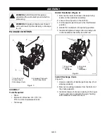
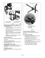
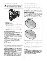
Страница 9: ... Install Discharge Chute Figure 5 1 Grease underside of discharge chute ring if not already greased 2 Remove mounting hardware from the bottom of the chute pedestal 3 Install discharge chute over opening in the auger housing and secure pedestal to auger housing with hardware removed in step 2 ASSEMBLY WARNING AVOID INJURY Read and understand the entire Safety section before proceeding WARNING Drop...

Страница 10: ...hipped with 5W 30 oil in crankcase Refer to Engine Manual for detailed instructions Fill Engine Fuel Tank Refer to Engine Manual for proper fuel type and tank capacity Check Function of all Controls Ensure unit runs and performs properly Refer to Operation Run in Attachment Belt 1 Start unit in a well ventilated area according to Starting and Shut Off on page 14 2 Engage attachment clutch lever an...

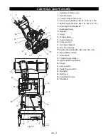
Страница 11: ...uger Gearcase 12 Clean out Tool 13 Oil Fill and Dipstick 14 Gas Tank and Cap 15 Electric Starter 932040 041 042 140 141 16 Recoil Starter Handle 17 Primer Bulb 18 Throttle Engine Stop 19 Ignition Switch push pull 20 Choke 21 Axle Lock Pin 22 Spark Plug and Wire 23 Runner s 24 Belt Cover 25 Fuel Shut off Valve 26 Handlebar CONTROLS AND FEATURES Figure 7 OS2420 OS0503 2 4 9 18 16 1 13 12 23 4 19 15 ...

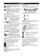
Страница 12: ...sier engine start Refer to Starting and Shut Off on page 14 Speed Selector Position the Speed Selector in the appropriate speed notch to control forward and reverse travel Forward 6 Fastest 1 Slowest Reverse 1 Slow 2 Fast IMPORTANT DO NOT change motion from forward to reverse with clutch engaged Forward speed can be changed without declutching Choke Control Knob 1 Choke Closed position chokes off ...

Страница 13: ... still frozen take to warm place until controls are free Chute Handle 932040 140 IMPORTANT If chute does not stay in set position adjust as directed in SERVICE AND ADJUSTMENTS on page 18 or repair before operation Rotate the Chute with Discharge Chute Handle Always stand opposite the direction of snow discharge when rotating the discharge chute IMPORTANT DO NOT force frozen chute controls If still...

Страница 14: ...wheel to allow for easier turning of the unit 4 Check Runners Check and adjust Runners SERVICE AND ADJUSTMENTS on page 18 Allow 1 8 in 3 mm between scraper blade and hard smooth surface s Allow 1 1 4 in 30 mm between scraper blade and uneven or gravel surfaces 5 Check Engine Fuel Crankcase Oil Check and add fuel if required Check that the engine crankcase oil is full using dipstick Refer to Engine...

Страница 15: ...ower cord from outlet then starter 12 Set throttle to Part Throttle or Slow position for travel or adaptation to outside temperature Set throttle to Fast position for normal operation Shut Off 1 Release Traction Drive Clutch Lever and allow unit to come to a complete stop 2 Run Impeller a few minutes after use to prevent freeze up of Impeller 3 Release Attachment Clutch Lever and wait for all movi...

Страница 16: ...perly adjust or repair before operation see SERVICE AND ADJUSTMENTS on page 18 CHECK CLUTCH SPRING ADJUSTMENT Make sure the attachment clutch and traction drive clutch are adjusted to the range specified in Attachment Clutch Brake Adjustment on page 21 CLEAN ENGINE Refer to Engine Manual for detailed instructions CHECK ENGINE OIL The engine crankcase oil should be checked every 5 hours of operatio...

Страница 17: ...with unit resting on a level surface 2 Add lubricant if required Allow oil to drain to level of plug and replace plug IMPORTANT Use only Ariens special gear lubricant L 2 Part Number 00008000 Gearcase filler plug may require an application of thread sealant with repeated servicing GENERAL LUBRICATION IMPORTANT Wipe each fitting clean before and after lubrication Do not wipe gearcase filler plug wi...

Страница 18: ...ners and tighten lock nuts SHEAR BOLTS IMPORTANT Use only Ariens shear bolts for replacement Use of any other type of shear bolt may result in severe damage to unit Occasionally a foreign object may enter the auger impeller housing and jam the auger breaking shear bolts Figure 15 which secure the auger to the shaft This allows auger to turn freely on the shaft preventing damage to gear drive For R...

Страница 19: ...ector into the first reverse speed f Engage the traction clutch Unit should move backward g Shut off unit 7 Adjust pivot pin on the shift rod as needed so unit travels forward when speed selector lever is in first forward position and backward when speed selector is in first reverse position 8 Connect the pivot pin to the speed selector arm with the hardware removed in step 1 ATTACHMENT DRIVE BELT...

Страница 20: ... 3 mm from belt with attachment clutch engaged or belt grabbing may occur causing impeller to rotate while attachment clutch is disengaged Figure 21 5 Adjust clutch per Attachment Clutch Impeller Brake Adjustment below 6 Replace chute crank and secure with spring pin 932041 042 141 509 510 511 7 Replace belt cover and secure with cap screws CAUTION Always support Sno Thro frame and housing when lo...

Страница 21: ...h arm Figure 22 c Pull up on the cable body to remove cable slack d Finger tighten mounting nuts and then loosen the top nut five turns e Tighten the bottom nut with a wrench 3 Check attachment clutch lever measurement a Start engine and run at full throttle b Slowly squeeze the attachment clutch lever until auger shaft begins to rotate c Measure the distance from the end of the clutch lever to th...

Страница 22: ...at auger impeller stops within 3 seconds after attachment clutch impeller brake lever is released TRACTION DRIVE CLUTCH ADJUSTMENT If drive slips adjust traction clutch to compensate for friction disc wear To test traction clutch Figure 23 1 Put unit in first forward speed 2 Without engine running push unit forward while slowly moving the traction drive clutch lever toward the handlebar 3 Measure ...

Страница 23: ... Remove three hex bolts and nuts holding friction disc to shift carrier 2 Remove the old friction disc Put the new friction disc in place flat side to the shift carrier 3 Reinstall the three bolts and nuts into the new friction disc and hub Torque to 5 6 lbf ft 6 8 to 8 13 N m Reinstall Friction Disc 1 Reinstall the shift carrier the small pinion gear and washer onto the hex shaft The washer goes ...

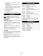
Страница 24: ...see Maintenance Touch up all scratched painted surfaces Remove weight from wheels by putting blocks under frame or axle When storing unit for extended periods of time remove all fuel from tank and carburetor run dry Refer to Engine Manual To obtain a complete parts manual find your model and serial number Then go to www ariens com or call 1 920 756 4664 STORAGE WARNING AVOID INJURY Read and unders...

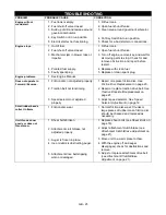
Страница 25: ... disc not adjusted properly 2 Traction belt not functioning 3 Speed selector not adjusted properly 1 Repair or replace friction disc See Friction Disc Replacement on page 23 2 Repair or replace traction drive belt See Traction Drive Belt Replacement on page 21 3 Adjust speed selector See Speed Selector Adjustment on page 19 Small rubber beads collect in frame 1 Friction disc wear 1 Normal friction...

Страница 26: ... qt L 2 0 1 96 3 5 3 3 3 5 3 3 2 0 1 96 3 5 3 3 2 0 1 96 3 5 3 3 3 5 3 3 Snow Clearing Width in cm 20 50 8 24 61 0 24 61 0 20 50 8 24 61 0 24 61 0 20 50 8 24 61 0 Chute Rotation Angle 195 Impeller Diameter in cm 12 30 5 Speed RPM Max min 1 1200 1200 1200 1200 1200 1200 1200 1200 Auger Diameter in cm 11 0 27 98 Speed RPM Max min 1 120 120 120 120 120 120 120 120 Auger Brake Yes Drive Disc O Matic S...

Страница 27: ...labor and parts except as noted below The duration of this warranty shall be ninety 90 days after the date of purchase or 1000 hours of use whichever comes first if any product is rented or leased 3 Year Limited Sno Thro Warranty Ariens Company Ariens warrants to the original purchaser that Sno Thro products manufactured by Ariens Company will be free from defects in material and workmanship for a...

Страница 28: ...nuine Ariens or Gravely brand service parts are not covered by this warranty Except as specifically warranted normal maintenance services and normal replacement items such as spark plugs oil oil filters air filters mufflers belts tires shoes runners scraper blades shear bolts mower blades mower vanes headlights light bulbs knives etc are not covered by this warranty except as noted below Mufflers ...

Страница 29: ......
Страница 30: ...Ariens Company 655 West Ryan Street P O Box 157 Brillion WI 54110 0157 920 756 2141 Fax 920 756 2407 www ariens com ...

Отзывы: