Page 31
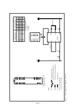
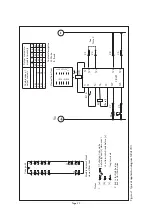
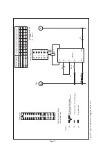
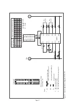
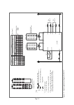
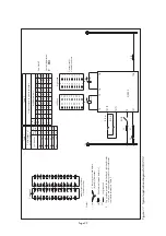
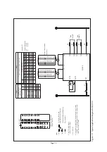
Figure 13: T
ypical application diagram MV
AJ 204
Left hand
Right hand
Combinations of output contacts
Table 1
(See Note 4)
Combination
Contact stacks viewed from front
L/h stack
R/h stack
20M
-
1
1
18M
2B
2
1
16M
4B
2
2
14M
6B
3
2
12M
8B
3
3
10M
10B
4
3
8M
12B
4
4
6M
14B
5
4
4M
16B
5
5
Table 2
Output contacts to module ter
minals
Module ter
minals
Cont. stack
1M
M
M
M
M
M
M
M
M
M
2B
M
M
M
M
B
M
M
M
M
3B
B
M
M
M
B
B
M
M
M
4B
B
B
M
M
B
B
B
M
M
5B
B
B
B
M
B
B
B
B
M
46
48
41
43
45
47
38
40
29
31
33
35
37
39
30
32
34
36
42
44
L/h
18
20
1
3
5
7
10
12
2
4
9
11
13
15
17
19
6
8
14
16
R/h
Contact description M:
Make
B:
Break
2 4 6 8 10 12 14 16 18 20
B
1 3 5 7 9 11 13 15 17 19
A
30 32 34 36 38 40 42 44 46 48
B
29 31 33 35 37 39 41 43 45 47
A
CT shor
ting links make
before (b) and (c) disconnect
long ter
minals
2 Link in for high burden Link out for low burden
Notes
1
(a)
(b)
(c)
3 Link for economising must be fitted.
4 The numbers quoted for left hand and right hand
stacks in T
able 1 are code numbers used for
cross references to module ter
minals in T
able 2.
shor
t ter
minals break before (c)
Case ear
th
Module ter
minal block
viewed from rear
11
1
3
5 7
9
13 15 17 19 21 23
25
27
2
4
6 8 10
14 16
18 20
22 24
26
28
12
39
29
31
33 35
37
41 43
45
30
32
34 36 38
42 44
46
40
47
48
49
50
51
52
53
54
55
56
(OP)
(OP)
RL1 20
RL3 20
Vx
23
21
24
22
See
Note 2
See
Note 3
28
27
PR
RL1-A
T4/T9
T3/T8
RL3-A
T27
T22
T24
T21
T23
T28
T20
T7
T2
T1
ZJ0393
26
T26
25
Reset
T25
RL1-B
T5/T6
T10/T11
RL3-B
RL1
RL3
(Reset coils)
Содержание MVAJ05
Страница 1: ...Types MVAJ05 10 20 Tripping and Control Relays Service Manual R8141B...
Страница 2: ......
Страница 4: ......
Страница 8: ......
Страница 36: ...Page 34...
Страница 39: ......


