Page 12
1.5
Installation
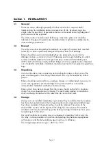
The installation should be clean, dry and reasonably free from dust and excessive
vibration. The site should preferably be well illuminated to facilitate inspection.
An outline diagram is normally supplied showing panel cut-outs and hole centres.
For individually mounted relays these dimensions will also be found in publication
R6141.
Publication R7012, Parts Catalogue and Assembly Instructions, will be useful when
individual relays are to be assembled as a composite rack or panel mounted
assembly.
Publication R6001 is a leaflet on the modular integrated drawout system of
protective relays.
Publication R6014 is a list of recommended suppliers for the pre-insulated
connectors.
Section 2. COMMISSIONING
2.1
Commissioning preliminaries
2.1.1
Electrostatic discharge (ESD)
The relay uses components which are sensitive to electrostatic discharges. When
handling the withdrawn module, care should be taken to avoid contact with
components and electrical connections. When removed from its case for storage
the module should be placed in an electrically conducting anti-static bag.
2.1.2
Inspection
Carefully examine the module and case to see that no damage has occurred
during transit.
Check that the relay serial number on the module, case and cover are identical,
and also check that the rating information is correct for the system.
2.1.3
Wiring
Warning
Exposed terminals may present a hazardous voltage unless
equipment is electrically isolated.
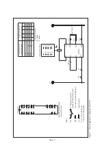
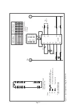
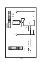
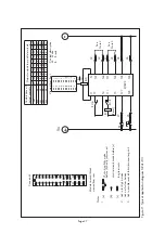
Check that the external wiring is correct to the relevant relay diagram and/or
scheme diagram. It is especially important that DC supplies are wired with the
correct polarity. The relay external connection diagram number is given on the
rating label inside the case.
2.1.4
External links
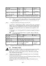
There are two external links as detailed in tables 1 and 2.
All trip relays are supplied as high burden. With the exception of MVAJ102, 202,
they may be converted to low burden by removing the link between case terminals
22 and 24.
Содержание MVAJ05
Страница 1: ...Types MVAJ05 10 20 Tripping and Control Relays Service Manual R8141B...
Страница 2: ......
Страница 4: ......
Страница 8: ......
Страница 36: ...Page 34...
Страница 39: ......


