background image


6. TECHNICAL 

SPECIFICATIONS 


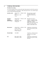
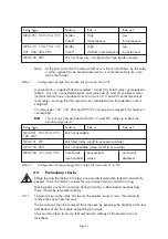
Protective fuse rating 

The recommended maximum rating of the external protective fuse for this equipment 
is 16A, Red Spot type or equivalent, unless otherwise stated in the technical data 
section of the product documentation. 

Insulation class: 

IEC 601010-1 : 1990/A2 : 2001 
Class I 

EN 61010-1: 2001 
Class I 

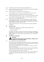
This equipment requires a 
protective (safety) earth 

connection to ensure user 
safety. 

Insulation 
Category 
(Overvoltage):


IEC 601010-1 : 1990/A2 : 1995 
Category III 
EN 61010-1: 2001 

Category III 
 

Distribution level, fixed 
insulation.  Equipment in this 
category is qualification tested 
at 5kV peak, 1.2/50

µ

s, 

500

Ω, 

0.5J, between all supply 

circuits and earth and also 
between independent circuits.  

Environment:


IEC 601010-1 : 1990/A2 : 1995 
Pollution degree 2 
EN 61010-1: 2001 
Pollution degree 2 

Compliance is demonstrated 
by reference to generic safety 
standards. 

Product Safety:


72/23/EEC 
 
 
EN 61010-1: 2001 

EN 60950-1: 2002 

Compliance with the European 
Commission Low Voltage 
Directive. 
Compliance is demonstrated 

by reference to generic safety 
standards. 


Содержание MVAJ05

Страница 1: ...Types MVAJ05 10 20 Tripping and Control Relays Service Manual R8141B...

Страница 2: ......

Страница 3: ...of the printed circuit board Avoid touching the electronic components printed circuit track or connectors 3 Do not pass the module to any person without first ensuring that you are both at the same e...

Страница 4: ......

Страница 5: ...13 2 3 Insulation tests 14 2 4 Operate reset operation 14 2 4 1 Self hand electrical and hand electrical reset 14 2 4 2 Self reset 2 5s delayed reset 15 2 5 Restoration of wiring 15 2 6 Problem analys...

Страница 6: ...3 Figure 6 Typical application diagram MVAJ102 24 Figure 7 Typical application diagram MVAJ103 25 Figure 8 Typical application diagram MVAJ104 26 Figure 9 Typical application diagram MVAJ105 27 Figure...

Страница 7: ...NG 3 3 EQUIPMENT OPERATING CONDITIONS 4 3 1 Current transformer circuits 4 3 2 External resistors 4 3 3 Battery replacement 4 3 4 Insulation and dielectric strength testing 4 3 5 Insertion of modules...

Страница 8: ......

Страница 9: ...earth terminal Note This symbol may also be used for a protective safety earth terminal if that terminal is part of a terminal block or sub assembly e g power supply NOTE THE TERM EARTH USED THROUGHOU...

Страница 10: ...otection Remove insulating strip from battery compartment 3 EQUIPMENT OPERATING CONDITIONS The equipment should be operated within the specified electrical and environmental limits 3 1 Current transfo...

Страница 11: ...inserted or withdrawn from the equipment whilst it is energised This is to avoid possible shock or damage hazards Hazardous live voltages may be accessible on the extender card Insertion and withdraw...

Страница 12: ...ory Overvoltage IEC 601010 1 1990 A2 1995 Category III EN 61010 1 2001 Category III Distribution level fixed insulation Equipment in this category is qualification tested at 5kV peak 1 2 50 s 500 0 5J...

Страница 13: ...when unpacking and installing the relays so that none of the parts are damaged or their settings altered and must only be handled by skilled persons Relays should be examined for any wedges clamps or...

Страница 14: ...hdrawn module care should be taken to avoid contact with components and electrical connections When removed from its case for storage the module should be placed in an electrically conducting anti sta...

Страница 15: ...ved if this feature is not required NB This link must remain fitted to MVAJ101 and 201 relays to enable the economising circuit Relay type Feature Link in Link out MVAJ051 053 054 055 Link not availab...

Страница 16: ...and its associated wiring may be insulation tested between all electrically isolated circuits all circuits and earth An electronic or brushless insulation tester should be used giving a dc voltage no...

Страница 17: ...tween 2 2 8s 2 5 Restoration of wiring Restore any external wiring connections that may have been disturbed during the above tests 2 6 Problem analysis Repeat Section 2 2 with particular attention to...

Страница 18: ...the armature Some mechanically operated contact gaps must be measured directly with feeler gauges at the contact tips The relay contact state is always defined with the relay in the reset position unl...

Страница 19: ...to 25 grammes Break Cut off contact bottom right hand viewed from front Force to break 25 to 30 20 to 25 grammes Contact gap measured 0 4 to 0 6 0 4 to 0 6 mm at the armature centre Section 5 SPARES W...

Страница 20: ...01 MVAJ103 01 hand reset 01 MVAJ104 01 electrical reset 01 MVAJ105 01 hand and electrical reset 20 contact versions 01 MVAJ201 01 self reset 01 MVAJ202 01 self reset 2s delayed reset 01 MVAJ203 01 ha...

Страница 21: ...CT shorting links make before b and c disconnect a b c long terminals short terminals break before c 1 2 Link in for high burden Link out for low burden Vx Viewed from front 1 3 5 7 9 11 A 2 4 6 8 1 2...

Страница 22: ...CT shorting links make before b and c disconnect a b c long terminals short terminals break before c 1 2 Link in for high burden Link out for low burden Vx Viewed from front 1 3 5 7 9 11 A 2 4 6 8 1 2...

Страница 23: ...Module terminal block viewed from rear 1 27 2 9 10 11 3 4 5 6 7 8 12 22 24 26 28 25 5M M M M M M 4M 1B B M M M M 3M 2B B M M B M 2M 3B B B M B M Combination of output contacts Output contacts to modul...

Страница 24: ...Module terminal block viewed from rear 1 27 2 9 10 11 3 4 5 6 7 8 12 22 24 26 28 25 5M M M M M M 4M 1B B M M M M 3M 2B B M M B M 2M 3B B B M B M Combination of output contacts Output contacts to modul...

Страница 25: ...6 8 CT shorting links make before b and c disconnect long terminals short terminals break before c 2 Link in for high burden Link out for low burden Notes 1 a b c 3 Link for economising must be fitte...

Страница 26: ...n M Make B Break 1 3 5 7 9 11 13 15 17 19 10 12 14 16 18 20 2 4 6 8 2 4 6 8 10 12 14 16 18 20 B 1 3 5 7 9 11 13 15 17 19 A Viewed from front 27 PR 25 CT shorting links make before b and c disconnect l...

Страница 27: ...Link in for high burden Link out for low burden 3 Do not fit link Contact description M Make B Break 10M M M M M M M M M M M 8M 2B B M M M M B M M M M 6M 4B B B M M M B B M M M 4M 6B B B B M M B B B M...

Страница 28: ...nt 3 Link to enable reset inhibitor economising coil CT shorting links make before b and c disconnect long terminals short terminals break before c 2 Link in for high burden Link out for low burden No...

Страница 29: ...12 14 16 18 20 B 1 3 5 7 9 11 13 15 17 19 A Viewed from front 27 Reset 25 CT shorting links make before b and c disconnect long terminals short terminals break before c RL1 10 OP RL1 A T1 T25 T2 T26...

Страница 30: ...10B 4 3 8M 12B 4 4 1 M M M M M M M M M M 2 B M M M M B M M M M 3 B B M M M B B M M M 4 B B B M M B B B M M 30 32 34 36 38 40 42 44 46 48 B 29 31 33 35 37 39 41 43 45 47 A Case earth Module terminal bl...

Страница 31: ...Contact stacks viewed from front Right hand Left hand 2 4 6 8 10 14 18 20 B 16 12 1 3 5 7 9 13 17 19 A 15 11 30 32 34 36 38 42 46 48 B 44 40 29 31 33 35 37 41 45 47 A 43 39 Case earth Module terminal...

Страница 32: ...35 37 39 41 43 45 47 A Contact stacks viewed from front 20M 1 1 18M 2B 2 1 16M 4B 2 2 14M 6B 3 2 12M 8B 3 3 10M 10B 4 3 8M 12B 4 4 6M 14B 5 4 4M 16B 5 5 OP OP RL1 10 RL3 10 Vx Case earth Module termi...

Страница 33: ...8 20 B 1 3 5 7 9 11 13 15 17 19 A 30 32 34 36 38 40 42 44 46 48 B 29 31 33 35 37 39 41 43 45 47 A CT shorting links make before b and c disconnect long terminals 2 Link in for high burden Link out for...

Страница 34: ...0 12 14 16 18 20 B 1 3 5 7 9 11 13 15 17 19 A 30 32 34 36 38 40 42 44 46 48 B 29 31 33 35 37 39 41 43 45 47 A Case earth Module terminal block viewed from rear 11 1 3 5 7 9 13 15 17 19 21 23 25 27 2 4...

Страница 35: ...Resetting Volts DC Diagram no Visual inspection Check operation at 60 LNV Check operating time at 100 LNV ms ms Check contact continuity Check electrical reset at 60 LNV Check reset time at 100 LNV M...

Страница 36: ...Page 34...

Страница 37: ...t Ref ___________________ Serial No ___________________ Date ___________________ 1 What parameters were in use at the time the fault occurred AC Volts ___________________ Main VT Test set DC Volts ___...

Страница 38: ...No Intermittent Yes No Time delayed Yes No Delete as appropriate By how long ___________________ 8 What indications if any did the relay show 9 Was there any visual damage 10 Any other remarks which m...

Страница 39: ......

Страница 40: ...AREVA T D s Automation Information Systems Business www areva td com T D Worldwide Contact Centre online 24 hours a day 44 0 1785 25 00 70 http www areva td com contactcentre Publication R8141B...

Отзывы: