Communications P12x/EN
CT/A96
COURIER DATABASE
MiCOM P120/P121/P122/P123
Page 5/248
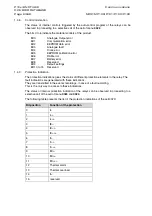
1.4.3 Status
word
Each response of a slave periphery contains an octet of status. This octet is resent by the
relay at the beginning of each message for signalling important data. The principal
workstation can be design for responding automatically to these important data.
The contained indications are the following:
Bit 0 - 1 =
Recording of disturbance available for retrieval
Bit 1 - 1 =
Change of the Unit status word
Bit 2 - 1 =
Change of the control status word
Bit 3 - 1 =
Relay busy, no response possible in time
Bit 4 - 1 =
Relay out of service
Bit 5 - 1 =
Recording of events available for retrieval
Bit 6 - 1 =
Switched alarm indicator
Bit 7 - 1 =
Switched tripping indicator
Only bits 3,4 and 7 are used for version
P121
.
Bits 1, 3 4, 5 and 7 are used for versions
P120, P122, P123
.
1.4.4
Unit status word
The unit status word is located in the menu
000C
.
Each bits pair of the Unit status word serves to indicate the status (position) of the unit
elements checked through the relay.
This functionality is not supported on
MiCOM P120, P121, P122
and
P123
relays.
1.4.5
Control status word
The Control status word is located in the cell of the menu
000D
.
It is used for transmitting the control information of the slave periphery to the central unit.
Nevertheless, the relays described in this manual are protection relays, which are not using
this control characteristic.
1.4.6
Logic input status word
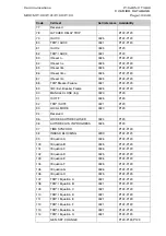
The logic control input status can be observed in proceeding to a selective call from the cell
of menu
0020
. The 2 bits inferior of the returned value indicating the status of each of the 2
logic inputs. This cell is accessible only in reading.
Bit 0:
logic input 1
Bit 1:
logic input 2
Bit 2:
logic input 3
Bit 3:
logic input 4
Bit 4:
logic input 5
1.4.7
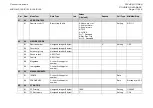
Output relay status word
The output relay status can be observed in proceeding to a selective call from the cell of
menu
0021
. The 8 bits inferior of the returned value indicating the status of each of the 5
output relays. This cell is accessible only in reading.
Bit 0:
relay 1 (TRIP)
Bit 1,2,3:
programmable relays n° 2,3,4
Bit 4:
Watchdog
Bit 5,6,7,8:
programmable relays n° 5,6,7,8
Содержание MiCom P120
Страница 1: ...MiCOM P120 P121 P122 P123 Overcurrent Relays Version 11 Technical Guide P12X EN T A96...
Страница 2: ......
Страница 4: ...P12x EN T A96 Technical Guide Contents Page 2 2 MiCOM P120 P121 P122 P123 BLANK PAGE...
Страница 13: ...Introduction P12x EN IT A96 MiCOM P120 P121 P122 P123 INTRODUCTION...
Страница 14: ......
Страница 16: ...P12x EN IT A96 Introduction Page 2 8 MiCOM P120 P121 P122 P123 BLANK PAGE...
Страница 22: ...P12x EN IT A96 Introduction Page 8 8 MiCOM P120 P121 P122 P123 BLANK PAGE...
Страница 24: ......
Страница 26: ...P12x EN IN A96 Handling Installation and Case Dimensions Page 2 10 MiCOM P120 P121 P122 P123 BLANK PAGE...
Страница 35: ...User Guide P12x EN FT A96 MiCOM P120 P121 P122 P123 USER GUIDE...
Страница 36: ......
Страница 40: ...P12x EN FT A96 User Guide Page 4 72 MiCOM P120 P121 P122 P123 BLANK PAGE...
Страница 108: ...P12x EN FT A96 User Guide Page 72 72 MiCOM P120 P121 P122 P123 BLANK PAGE...
Страница 109: ...Menu Content Tables P12x EN HI A96 MiCOM P120 P121 P122 P123 MENU CONTENT TABLES...
Страница 110: ......
Страница 112: ...P12x EN HI A96 Menu Content Tables Page 2 68 MiCOM P120 P121 P122 P123 BLANK PAGE...
Страница 179: ...Technical Data P12x EN TD A96 MiCOM P120 P121 P122 P123 TECHNICAL DATA AND CHARACTERISTIC CURVES...
Страница 180: ......
Страница 221: ...Application Guide P12x EN AP A96 MiCOM P120 P121 P122 P123 APPLICATION GUIDE...
Страница 222: ......
Страница 226: ...P12x EN AP A96 Application Guide Page 4 80 MiCOM P120 P121 P122 P123 BLANK PAGE...
Страница 302: ...P12x EN AP A96 Application Guide Page 80 80 MiCOM P120 P121 P122 P123 BLANK PAGE...
Страница 304: ......
Страница 305: ...Communications P12x EN CT A96 MiCOM P120 P121 P122 P123 MODBUS DATABASE MiCOM P120 P121 P122 P123 VERSION V11 A...
Страница 306: ......
Страница 367: ...Communications P12x EN CT A96 MiCOM P120 P121 P122 P123 COURIER DATABASE MiCOM P120 P121 P122 P123 VERSION V11 A...
Страница 368: ......
Страница 370: ...P12x EN CT A96 Communications COURIER DATABASE Page 2 248 MiCOM P120 P121 P122 P123 BLANK PAGE...
Страница 514: ...P12x EN CT A96 Communications COURIER DATABASE Page 146 248 MiCOM P120 P121 P122 P123...
Страница 515: ...Communications P12x EN CT A96 MiCOM P120 P121 P122 P123 IEC 60870 5 103 MiCOM P120 P121 P122 P123 VERSION V11 A...
Страница 516: ......
Страница 518: ...P12x EN CT A96 Communications IIEC 60870 5 103 Page 2 248 MiCOM P120 P121 P122 P123 BLANK PAGE...
Страница 536: ...P12x EN CT A96 Communications IEC 60870 5 103 Page 20 248 MiCOM P120 P121 P122 P123...
Страница 537: ...Communications P12x EN CT A96 MiCOM P120 P121 P122 P123 DNP 3 0 DATABASE MiCOM P120 P121 P122 P123 VERSION V11 A...
Страница 538: ......
Страница 540: ...P12x EN CT A96 Communications DNP 3 0 Database Page 2 248 MiCOM P120 P121 P122 P123 BLANK PAGE...
Страница 553: ...Commissioning and Maintenance P12x EN CM A96 MiCOM P120 P121 P122 P123 COMMISSIONING AND MAINTENANCE GUIDE...
Страница 554: ......
Страница 573: ...Connection Diagrams P12x EN CO A96 MiCOM P120 P121 P122 P123 CONNECTION DIAGRAMS...
Страница 574: ......
Страница 579: ...Commissioning Test Record Sheets P12x EN RS A96 MiCOM P120 P121 P122 P123 COMMISSIONING TEST RECORD SHEETS...
Страница 580: ......
Страница 582: ...P12x EN RS A96 Commissioning Test Record Sheets Page 2 60 MiCOM P120 P121 P122 P123 BLANK PAGE...
Страница 640: ...P12x EN RS A96 Commissioning Test Record Sheets Page 60 60 MiCOM P120 P121 P122 P123 BLANK PAGE...
Страница 642: ......
Страница 644: ...P12x EN VC A96 Hardware Software Version History and Compatibility Page 2 26 MiCOM P120 P121 P122 P123 BLANK PAGE...
Страница 667: ......


