Important:
Observe interlock conditi-
ons (see chapter 7.2).
7.5.1 Withdrawable part for PIX
switchgear panels
Move circuit-breaker from
disconnected into service
position by hand:
Initial situation:
Circuit-breaker OFF
Earthing switch
OFF
1. Insert crank handle with integra-
ted slip coupling (Fig. 7.6) and
move it clockwise to its stop or
until the slip coupling reacts; the
circuit-breaker is racked into its
service position. Observe the po-
sition indicator on the switchgear
panel.
2. Remove crank handle.
Move circuit-breaker from
service into disconnected
position by hand:
Initial situation:
Circuit-breaker OFF
1. Insert crank handle with integra-
ted slip coupling (Fig. 7.6) and
move it counter-clockwise to its
stop or until the slip coupling re-
acts; the circuit-breaker is racked
into its disconnected position.
Observe the position indicator on
the switchgear panel.
2. Remove crank handle.
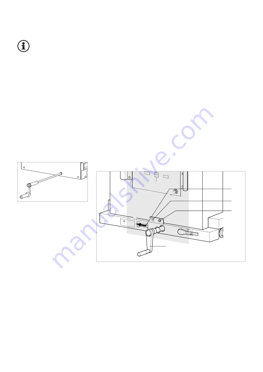
Fig. 7.6
Crank handle to rack the circuit-breaker
in and out
Move circuit-breaker from
disconnected into service
position by hand:
Initial situation:
Circuit-breaker OFF
Earthing switch
OFF
1. Push interlocking slide (Fig. 7.7,
item 1) to the left to free the in-
sertion opening.
2. Insert crank (2) and turn it clock-
wise to its stop. The circuit-brea-
ker moves into service position.
The position indicator must indi-
cate "I" (3).
3. Remove crank.
7.5 Actuate withdrawable part
Fig. 7.7
Moving the withdrawable part in PIX High Current Panels
1
Interlocking slide to free the insertion opening
2
Crank
3
Position indicator “I”: Withdrawable part in service position
4
Position indicator "O": Withdrawable part in disconnected position
1
2
3
4
7.5.2 Withdrawable part for PIX high current switchgear panels
Move circuit-breaker from
service into disconnected
position by hand:
Initial situation:
Circuit-breaker OFF
1. Push interlocking slide (Fig. 7.7,
item 1) to the left to free the in-
sertion opening.
2. Insert crank (2) and turn it coun-
ter-clockwise to its stop. The cir-
cuit-breaker moves into discon-
nected position. The position in-
dicator must indicate "O" (4).
3. Remove crank.
21
7.5.3
Motor drive in the withdrawable part
Enter command to the local or remo-
te control. Observe position indica-
tor.
Содержание HVX -F
Страница 30: ...Notes...
Страница 31: ......


