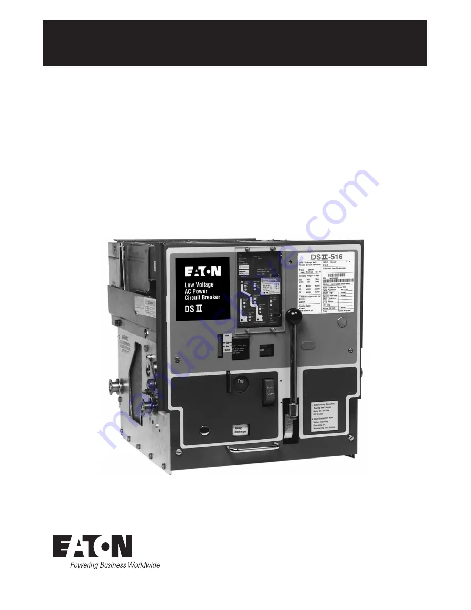
manualshive.com logo in svg
background image

Effective July 2010
Supersedes July 1997
IB694C694-02

Instructional Book 

IB694C694-03

Instructions for Installation, 

Operation and Maintenance of Low 

Voltage Power Circuit Breakers Types 

DSII and DSLII

Содержание DSII Series

Страница 1: ...Effective July 2010 Supersedes July 1997 IB694C694 02 Instructional Book IB694C694 03 Instructions for Installation Operation and Maintenance of Low Voltage Power Circuit Breakers Types DSII and DSLII...

Страница 2: ...DSII Drawout Fuse Trucks and their accessories consult the applicable Instruction Book or other descriptive publications For application information consult Eaton see applicable De scriptive Bulletins...

Страница 3: ...y Moving Contact Assembly 17 3 4 2 Primary Stationary Contact Assembly 18 3 5 Interphase Barriers 18 3 6 DE ION Arc Chutes Interrupter Assemblies 20 3 7 Electronic Tripping System 20 3 7 1 Electronic...

Страница 4: ...LII Current Limiters 48 4 6 2 Blown Limiter Indicator 48 4 6 3 Fuse Truck 48 4 6 4 Fuse Truck Installation and Use 49 4 6 5 Fuse Replacement 49 4 6 6 Blown Fuse Indicator 49 SECTION 5 INSPECTION AND M...

Страница 5: ...ounted 25 3 16 Power Operated DSII Breaker Front Cover Removed 26 3 17 Latch Check Switch Operation 27 3 18 Undervoltage Trip Attachment Operation 27 3 19 Overcurrent Trip Switch Operation 28 3 20 Clo...

Страница 6: ...echanism 58 5 8 Left Side of Mechanism Lubrication Points 60 5 9 Right Side of Mechanism Lubrication Points 60 5 10 Shunt Trip Device Lubrication 60 5 11 Spring Release Device Lubrication 60 5 12 Trip...

Страница 7: ...ed current limiters The purpose of the current limiters is to extend the interrupting rating of the standard DSII breaker Figure 1 3 The Type DSII breaker is a four position drawout Connect Test Disco...

Страница 8: ...and the associated hazards should be permitted to work on the equipment Additionally only quali fied personnel should be permitted to install or operate the equipment 2 Always be certain that the pri...

Страница 9: ...dance with established safety practices 1 5 OTHER PUBLICATIONS AND DOCUMENTATION In addition to this instruction manual other printed information and documentation is available and supplied as appropr...

Страница 10: ...3 Type DSLII Breaker with Integral Current Limiters Figure 1 4 DSII Breaker Shown on Compartment s Captive Extension Rails Effective July 2010 Instructional Book IB694C694 03 10 eaton corporation www...

Страница 11: ...ed to be easily lifted from the shipping container using the appropriate lifting yoke and an overhead or portable lifting device CAUTION DO NOT ATTEMPT TO LIFT BREAKERS WITH ORDINARY CRANE HOOKS ROPES...

Страница 12: ...SE BARRIERS ASSIST IN MAINTAINING PROPER CLEAR ANCES AND MUST BE IN PLACE AT ALL TIMES DURING CIRCUIT BREAKER OPERATION WITHIN A BREAKER COMPARTMENT Remove the three arc chutes which are mounted on to...

Страница 13: ...e levering crank in the direction required to get the levering arms in the REMOVE position Carefully push the circuit breaker into the breaker compartment until it physically stops Begin turning the l...

Страница 14: ...ure that it will be isolated or carrying NO current before it can be levered to the DISCONNECT position Dummy elements require the same size compartment as an equivalent Type DSII breaker of the same...

Страница 15: ...DSII Circuit Breakers are available with either a manually operated or electrically operated two step stored energy mechanism It provides positive control of the closing instant Six continuous current...

Страница 16: ...pping system True RMS sensing is provided for proper correlation with thermal characteristics of conductors and equipment 3 2 Type DSLII Limiter Circuit Breaker Type DSLII Circuit Breakers are coordin...

Страница 17: ...AMAGE BODILY INJURY AND OR DEATH 3 3 Basic Breaker Assembly The basic breaker assembly includes a chassis a con trol panel an operating mechanism a tripping system a levering in device drawout breaker...

Страница 18: ...the magnetic fields of the currents in each arcing contact finger causes the fingers to be attracted toward each other when closing against fault currents This results in a blow on action on the arcin...

Страница 19: ...nsulating Link Adjusting Nut Pivot Block Moving Main Contact Assembly Figure 3 4 Type DSII 308 Pole Unit Assembly Front View Upper Terminal Lower Terminal Sensor Removed Figure 3 5 Type DSII 308 Pole...

Страница 20: ...ing the arc In addition to steel plates the larger arc chutes include hard arc resistant glass polyester plates These plates produce turbulence in the exhaust gases above the steel plates and Moving A...

Страница 21: ...ion Settings Trip Actuator 600 Ohms Nominal Resistance Typical DSII Type Circuit Breaker Sensors Alternate ground locations may be required to meet installation requirements Figure 3 10 TypicalType DS...

Страница 22: ...ate with the load or system refer to the specific trip unit instruction book 3 7 2 Sensors Three current sensors are installed at the rear of the circuit breaker on the lower studs directly behind the...

Страница 23: ...hand This is accomplished through the use of a front mounted spring charge handle The spring charge handle used with manually operated circuit breakers is significantly longer than the handle used wi...

Страница 24: ...ring release latch Like the manually operated circuit breaker the power operated circuit breaker can also be closed manually by pushing on the front control panel close bar Figure 3 3 Like the manuall...

Страница 25: ...e spring release coil is energized through the anti pump relay the motor cut off switch and a normally closed b auxiliary switch contact which operates the spring release latch to release the closing...

Страница 26: ...r five normally open and five normally closed contacts are available for use on both manually and power operated breakers 3 10 7 UndervoltageTrip Attachment UVTA The undervoltage trip attachment is op...

Страница 27: ...due to phase or ground overcurrent Tripping by the trip plate shunt trip device undervoltage trip device and other such methods does not cause it to operate Pole Shaft Breaker Closed Position Breaker...

Страница 28: ...ounter used to provide a record of the number of breaker operations Figure 3 3 The counter is linkage connected to the pole shaft Actuator Cam Normal Position Overcurrent Trip Indication Position Figu...

Страница 29: ...ndicate Spring Charged CAUTION DO NOT RELEASETHE CHARGING HANDLE BEFORETHE CHARGING OPERATION IS COMPLETED IFTHE HANDLE IS RELEASED BEFORETHE OPERATION IS COMPLETED THE HANDLE WILL RETURNTO ITS NORMAL...

Страница 30: ...s previously detailed in Paragraph 4 1 It is possible to manually recharge the closing springs im mediately after closing the breaker and before it has been tripped open This results in the springs lo...

Страница 31: ...Refer to Figure 4 5 The basic elements are mounted on the crank shaft 8 This is a straight shaft with four flats machined on it and a crank arm 11 attached to each end Each crank arm connects to its c...

Страница 32: ...Charge Handle Stop Roller Crank Shaft Motor Crank and Handle Spring Release Latch Emergency Charge Device Moving Contact Assembly Spring Release Device Crank Arm Insulating Link Oscillator Pawl Closin...

Страница 33: ...Pawl Lifter Trip Shaft Ratchet Bushing Oscillator Pawl Close Cam Ratchet Wheel Oscillator Motor Cut Off Switch Cam Hold Pawl Mechanism Side Frame Right Hand Crank Shaft Oscillator Mechanism Side Frame...

Страница 34: ...Spring Spring End Motor Crank Roller Crank Shaft Ratchet Wheel Ratchet Wheel Pin Hold Pawl Figure 4 6 Power Operated Spring Charge Details a Spring Charged Note Main cam position for this crank shaft...

Страница 35: ...are released to close the breaker When the breaker closes the b contact opens to cut off the spring release coil SR and motor MOT and the limit switch LS contacts reset If the close contact CS C is m...

Страница 36: ...ct Pivot Pin Main Drive Link Main Roller Spring Release Latch Insulating link Adjusting Stud and Lockout Insulating Link Mechanism Side Frame Hardened Latch Surfaces b Breaker Open Spring Charged Spri...

Страница 37: ...breaker open The breaker is now ready to be closed Closing is started by counterclockwise rotation of the spring release latch Figure 4 7b This removes the hold on the close cam stop roller and allow...

Страница 38: ...Attachment Y Anti Pump Relay UVTA Undervoltage Trip Attachment Optional BOTTOM LEFT ROW When Viewed From Front of Breaker LS Contacts N C Contacts Open When Closing Springs are Fully Charged N O Cont...

Страница 39: ...e type of operation it causes some extra shock on the mechanism parts Therefore trip free operations should be avoided The trip shaft can be rotated to trip the breaker in a number of ways 1 Breaker T...

Страница 40: ...y or manually 4 The breaker can be withdrawn from the compartment by direct pull The levering device is not engaged with the cradle at this point 5 The levering device arms are in a horizontal positio...

Страница 41: ...Shutter Pivot Pin Pole Shaft Levering Device Shaft Trip Shaft Trip Shaft Pin Tripping Tab Trip Plate Trip Plate Hook Levering Device Crank Handle b Shutter Trip Plate Held in Tripped Position Figure...

Страница 42: ...being driven in either direction by the levering device or while it is standing in any intermediate position between TEST and CONNECT or DISCONNECT Figure 4 11a shows the shutter and trip plate for no...

Страница 43: ...s to its closed position when the levering crank is removed The levering device arms are now almost vertically downward Figure 4 12c shows the DISCONNECT position Here the cam also rotates so as to bl...

Страница 44: ...ed the interlock plate can be rotated freely on the shaft about 10 degrees This is because the wide slot is considerably wider than the drive pin If the interlock screw is in place in the narrow slot...

Страница 45: ...Interlock Screw See Paragraph 4 5 7 Interlock Plate Assembly Pin A Drive Pin Pin B Interlock Screw Close Bar Levering Device Shaft Close Bar Pivot Narrow Slot Close Bar Cam Wide Slot Levering Device...

Страница 46: ...e bar is pushed the upper end of the spring release latch link swings free to the right because the indicator pin is not there to stop it Consequently no force is applied to the vertical arm of the be...

Страница 47: ...ver behind the notch in the padlock plate With the padlock plate held forward the padlock interlock lever cannot move Consequently the projection from the trip plate is held in the slot in the padlock...

Страница 48: ...For this reason there is no fixed mounted version of the DSLII circuit breaker 4 6 2 Blown Limiter Indicator The blown limiter indicator provides a visual indication on the front of the DSLII circuit...

Страница 49: ...art ment the fuses can be removed by unbolting them from the conductors on the fuse truck This is a relatively uncom plicated procedure on the DSII FT40 fuse truck because there is sufficient working...

Страница 50: ...ped Position Figure 4 17 Blown Limiter Indicator Figure 4 19 DSII FT32 FuseTruck Rear View Figure 4 18 DSII FT32 FuseTruck Front View Figure 4 20 DSII FT32 FuseTruck Front Cover Removed Effective July...

Страница 51: ...es a valuable histori cal reference on equipment condition over time 5 2 General Cleaning Recommendations Circuit breaker cleaning activities should be a part of an overall activity that includes the...

Страница 52: ...ween the stationary arcing contacts and the center section of the cage If this dimension is not 02 inches or greater the stationary arcing contacts should be replaced NOTICE Be certain that all barrie...

Страница 53: ...mensions should be approximately equal If not trip the breaker and adjust the fixed contact system until alignment is obtained Tighten the screws and contacts as described in Paragraph 5 5 2 5 4 5 Arc...

Страница 54: ...face is chipped distorted or broken it should be replaced 5 5 Factory Adjustments NOTICE These adjustments are required only when a major overhaul has been performed not during normal maintenance pro...

Страница 55: ...ife of the breaker Factory settings adjustments should only be necessary when parts are reassembled after dismantling as described in Paragraphs 5 5 1 and 5 5 2 Maintenance adjustments should be made...

Страница 56: ...g screw clockwise until the breaker trips This is the no overlap position 3 Conclude by rotating the adjusting screw four turns in a counterclockwise direction 5 5 2 Breaker Open Position Stop Adjustm...

Страница 57: ...ce Main Drive Link Shunt Trip Armature Trip Shaft Adjusting Screw Shunt Trip Coil Trip Actuator Figure 5 5 ShuntTrip Details ShowingTrip Shaft Adjustment Anti Rebound Latch Open Position Stop adjustab...

Страница 58: ...he exact position with respect to the worm gear position for proper interlock operation This is achieved when the threaded worm shaft bottoms in the stop nut and the interlock cam is in the con nected...

Страница 59: ...should be operated a minimum of five times before being put in service 5 6 2 Lubricant Location NOTICE All parts of the levering mechanism have sufficient lubrication and should not require any furthe...

Страница 60: ...brication Points 4 Figure 5 10 ShuntTrip Device Lubrication 9 2 Figure 5 9 Right Side of Mechanism Lubrication Points 6 Figure 5 11 Spring Release Device Lubrication Effective July 2010 Instructional...

Страница 61: ...7 7 Figure 5 12 Trip Shaft Lubrication Effective July 2010 Instructional Book IB694C694 03 61 eaton corporation www eaton com...

Страница 62: ...d item number as shown in the Renewal Parts Data Book Also include the breaker type shop order number or style number as shown on the nameplate on the front cover of the circuit breaker Some of the de...

Страница 63: ...Effective July 2010 Instructional Book IB694C694 03 63 eaton corporation www eaton com...

Страница 64: ...ies or other contractual agreement between Eaton and the purchaser THERE ARE NO UNDERSTANDINGS AGREEMENTS WARRANTIES EXPRESSED OR IMPLIED INCLUDING WARRANTIES OF FITNESS FOR A PARTICULAR PURPOSE OR ME...

Отзывы: