the relevant figure. Apply the supplied sealant to the entire
perimeter of the hob and insert it into the fitment hole (for
sizing see
Fig.4B
). Lock the appliance on the work top using
the 4 supports and the
"V"
holes, rotating them based on
top thickness
(Fig.4A)
. After installation, if the bottom part
of the appliance is not accessible, it is mandatory to install a
separator panel
"G" (Fig.7A)
following indicated distances
(Fig.7B)
.
If the appliance is installed over an oven the panel is not
necessary
(Fig.8A - Fig.8B)
.
Important:
If there is an oven under the induction hob it is
advisable for it to have a cooling fan. Do not use the induction
hob while
PYROLITIC
cleaning is in process.
Warning:
to allow the circulation of as much fresh air as neces-
sary, there must be at least
40 mm
between the induction hob
module and any appliance installed under it
(Fig.8B)
.
In any event, adequate aeration must be provided.
To allow fresh air circulation there must be openings in the
kitchen furniture
(Fig.7A - Fig.8A)
of the sizes indicated in
Fig.7B - Fig.8B
.
Electrical connections (Fig.9):
Before making the electrical connections, check that:
- The ground cable is 2 cm longer than the other cables;
- The system ratings meet the ratings indicated on the identi-
fication plate fixed on the lower part of the worktop;
- The system is fitted with efficient earthing compliant to the
laws and regulations in force. Earthing is obligatory by law.
If the appliance is not fitted with a cable, use type:
"H05V2V2-F"
for a power level of up to 6400 Watts. The cross-
section of the cable should be at least 2.5 mm², or 4 mm² for
greater power levels. The cable should never reach a tem-
perature which is 50°C above the temperature of the room in
which it is installed. The appliance is designed for permanent
connection to the electricity supply and should therefore be
fitted with an omnipolar switch which has a minimum opening
of 3 mm between contacts. The switch should be suitable for
the charge indicated on the appliance data plate and must
conform to all current legislation (the yellow/green earth wire
must not be interrupted by the switch).
The omnipolar switch must be easy to reach once the instal-
lation process has been completed.
USE AND MAINTENANCE
• Use
(Fig.2):
A =
ON/OFF
button
B =
Key
button
B1 = Key button ON/OFF
indicator
C =
"-"
button
D = "+"
button
E = Heating plate
selection button
L =
Display.
Cooktop Ignition:
- Verify that
"B1"
led is off before turning the equipment on;
otherwise, turn it off by pressing the
"B"
key button for ap-
proximately 2 seconds.
- Next, select the
"A"
button.
- An acoustic signal "BEEP" is emitted after which on all displays
"L"
decimal points appear
"•"
. If no operation is performed
within this time interval, the hob switches off.
Heating Plate Ignition:
- A heating plate can be turned on by selecting one of the
"E"
buttons. A blinking zero will appear on the display.
- Use
"+"
or
"-"
buttons to regulate the power level.
- If the display shows zero and the
"-"
is pressed, the power
level goes directly to 9. The display will show the respective
numbers; those in the interested area, the shade will be bright,
while the other areas will be a lighter shade.
- If after about 10 seconds no operation is carried out, display
shade goes back to the initial one. The hob will continue its
normal cooking.
- If the power level is set at zero, the cooking zone will shut
off.
Shutting off the heating plates:
- Select the cooking zone using the button
"E"
. The display will
show the respective numbers; those of the interested area will
be brighter, while the other ones will be a lighter shade.
- Press the
"+"
and
"-"
buttons simultaneously otherwise, by
selecting only the
"-"
button, it is possible to bring the power
level to zero.
- All operations will be combined with a "BEEP" acoustic
signal.
- When a cooking zone
"E"
is brought to the OFF position and
the glass top temperature is greater than approximately 50°,
the display
"L"
of the interested zone will signal a fixed
"H"
.
Warning:
To prevent damage being inflicted on the electronic circuits,
the hob is fitted with an overheating safety system.In
situations where the appliance is used at high power levels for
a prolonged period of time, the hob may switchoff one or more
of the activated zones temporarily, until the temperatures
return to the set levels. The display of the zone temporarily
shut off will show a
"C"
alternated with the power level. Once
the temperatures are back within the limits, a flashing letter
"C"
will appear.
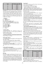
Power limiting:
The hob is has four burners, it is equipped with a power
limitation system at 7200, 2800, 3500 or 6000 Watts.
The product can be set up with the following instructions:
- Disconnect and reconnect the appliance to the domestic
power supply.
- Select the
"B"
button within 30 seconds after the reconnec-
tion to the domestic power supply.
- Simultaneously press the
"E1"
and
"E3"
buttons.
- Once the "BEEP" acoustic signal is heard, the
"E2"
and
"E3"
displays with show the power level of the hob.
- Use the
"+"
or
"-"
buttons on the
"E2"
and
"E3"
display,
all possible levels the hob can be set at will appear in
sequence.
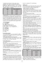
Code:
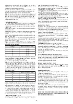
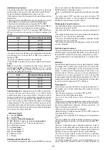
Maximum Power Watts
7 2
7200 W
2 8
2800 W
3 5
3500 W
6 0
6000 W
- Once the desired power level has been set, press the
"E1"
and
"E3"
buttons simultaneously, then disengage the key button
"B"
.
- The cooktop is adjusted to the desired power.
- To change the power again, repeat the whole procedure.
Nota:
If the hob has 3 burners instead, use the
"E1"
and
"E2"
buttons. Use the
"+"
or
"-"
buttons on the
"E2"
and
"E3"
display, all possible levels the hob can be set at will appear
in sequence.
- 28 -
Содержание PI58F
Страница 2: ......
Страница 4: ... Fig 2 4 ...
Страница 5: ... Fig 3 5 ...
Страница 6: ... Fig 4 6 ...
Страница 7: ... Fig 7 Fig 5 Fig 6 7 ...
Страница 8: ... Fig 8 Fig 9 8 ...
Страница 75: ......
Страница 76: ...3LIP0275 ...


