ARC-19509
ArcVision Technology Corp.
3
3. Installation
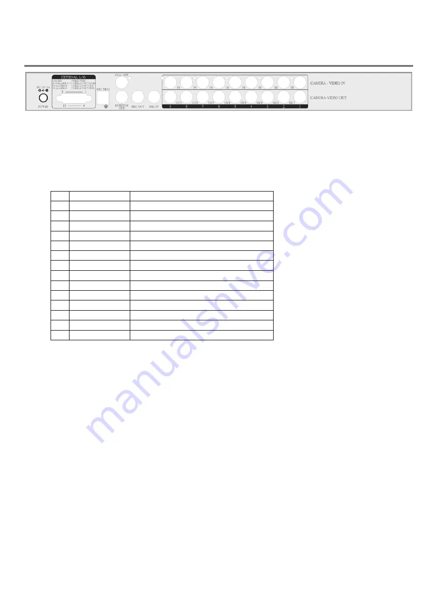
Back Panel
3.1 Power Supply
DC 12V ±10%, 830mA, DC 12V/1A switching mode power adapter is recommended.
3.2 ALARM I/O
There is a DB15 connector on the left side of the back panel, which is connected to the external alarm sensor and time lapse VCR
trigger input.
1
GND
Ground
2
ALARM IN-1
External alarm input 1
3
ALARM IN-2
External alarm input 2
4
ALARM IN-3
External alarm input 3
5
ALARM IN-4
External alarm input 4
6
ALARM IN-5
External alarm input 5
7
ALARM IN-6
External alarm input 6
8
ALARM IN-7
External alarm input 7
9
GND
Ground
10
REC TRIG
External recoder trigger input
11
RELAY OUT-COM
Relay output COM terminal
12
RELAY OUT-N.C.
Relay output normal close terminal
13
RELAY OUT-N.O.
Relay output normal open terminal
14
ALARM IN-9
External alarm input 9
15
ALARM IN-8
External alarm input 8
3.3 REC TRIGGER INPUT PORT
REC trigger input port is on the right side of the DB15. It is for VCR/DVR trigger signal input.
3.4 VIDEO OUT
3.4.1 MONITOR OUT
Connect the BNC connector for
“
MONITOR OUT
”
on the Mutiplexer and the other part to
“
VIDEO IN
”
on the Monitor.
3.4.2 CALL OUT
Connect the BNC connector for
“
CALL OUT
”
on the Mutiplexer and the other part to
“
VIDEO IN
”
on another Monitor.
3.4.3 REC OUT
Connect BNC connector for
“
REC OUT
”
on the Multiplexer and the other part to
“
VCR IN
”
on the VCR.
3.5 REC IN
Connect the BNC connector for
“
REC IN
”
to the VCR for
“
VIDEO OUT
”
on the VCR.
3.6 VIDEO IN & LOOP OUT
The camera line is connected to Camera-Video IN and the nine-channel loop-out path is supplied for alternative usage.
ALARM
ALARM


