37
3. Slide the insulators away from the
adjusters; then loosen the jam nut
securing each throttle cable adjuster.
Rotate each adjuster clockwise until
each piston valve bottoms in the pis-
ton valve bore.
4. In turn on each carburetor, place a
finger lightly against the side of the
piston valve; then rotate the carbure-
tor adjuster counterclockwise until
slight upward movement of the
valve is noted.
5. Check to make sure the valves start
to open at the exact same moment by
placing a thumb and finger against
the valves; then lightly compress the
throttle lever.
NOTE: If an individual piston valve
starts to open before another, rotate
the adjuster on the valve which is
lifting first clockwise, just enough to
synchronize the valves. Recheck by
repeating steps 2-5.
6. With the piston valves synchronized,
tighten the adjuster jam nuts
securely; then slide the insulators
onto the adjusters.
NOTE: There must be free-play in
the throttle lever.
7. In turn on each carburetor, place a
finger against the piston valve.
Rotate the idle speed screw clock-
wise until it contacts the valve.
8. Compress the throttle lever to the
full-open position; then rotate each
idle speed screw clockwise 2 com-
plete turns. Release the throttle
lever.
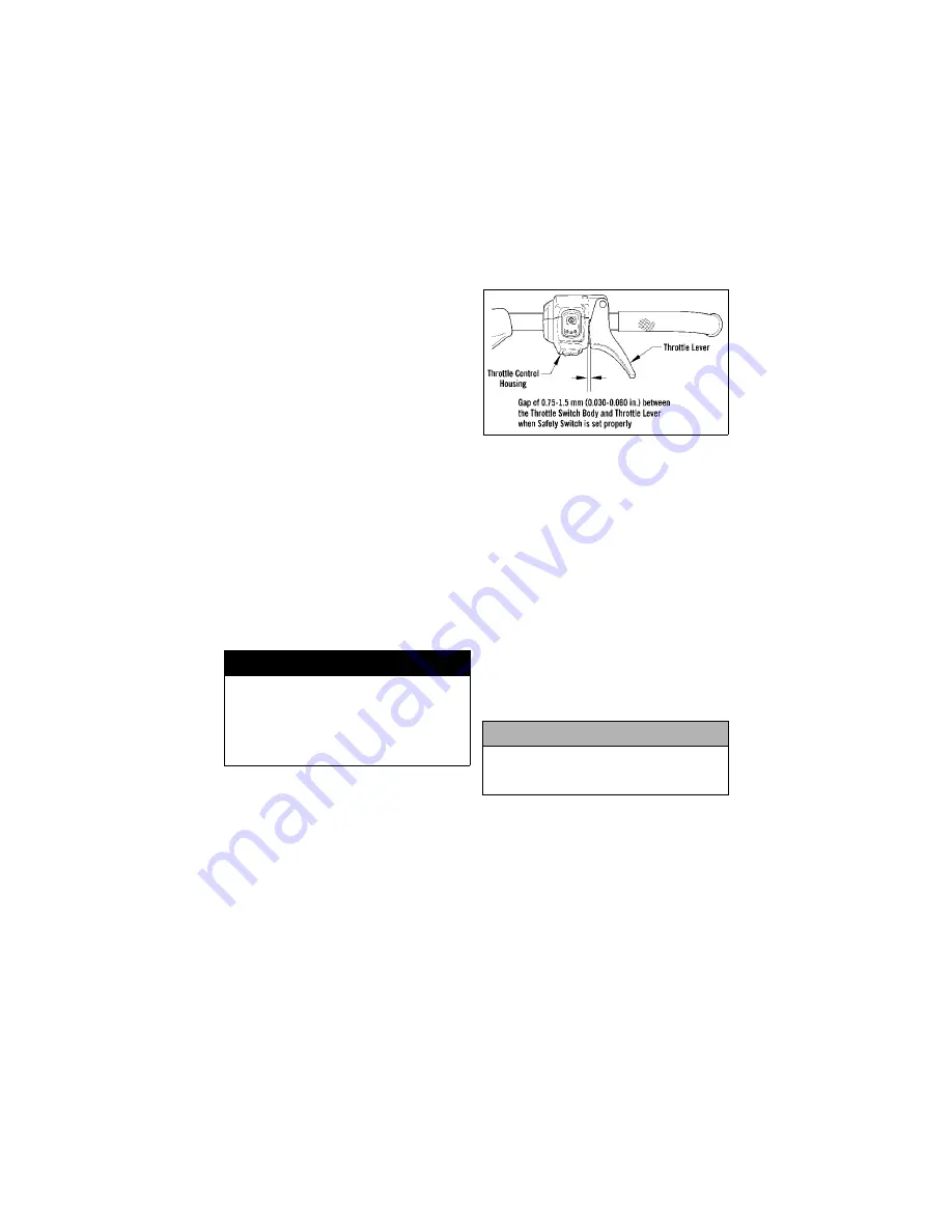
NOTE: There must be 0.75-1.5 mm
(0.030-0.060 in.) free-play between
the throttle lever and the control
housing.
9. At this point, there must be 0.75-1.5
mm (0.030-0.060 in.) of cable free-
play gap in the throttle lever. If there
is no cable free-play in the throttle
lever, the throttle safety switches will
not function properly, and the engine
will cut out in the idle position.
0741-518
NOTE: If cable free-play gap is not
correct, rotate each adjuster an
equal amount until recommended
free-play is achieved. Each piston
valve must be resting against the tip
of its idle speed screw.
NOTE: If throttle cable free-play is
incorrect, the carburetor safety
switches will be activated prema-
turely and the engine will not start.
Fine-Tuning Pilot Air
Screws and Idle Speed
Screws (External)
1. While counting the rotations, care-
fully rotate the pilot air screws
clockwise until lightly seated.
2. Rotate the pilot air screws counter-
clockwise the exact number of rota-
tions ± 1/4 turn from the seated
position as an initial setting.
3. Install the air-intake silencer boots
taking care that the boots are properly
positioned and that the boots are not
“folded” in the air-intake silencer
causing a restriction of air flow.
4. With the snowmobile on a shielded
safety stand, start the engine, release
the brake lever lock, and thoroughly
warm up.
! WARNING
Be sure to tighten the adjuster jam
nuts securely. If an adjuster jam nut
is not tightened, the adjuster can
rotate out of the carburetor cap
causing the piston valve not to
return to the full-closed position.
CAUTION
Do not force a pilot air screw when
rotating it clockwise; damage to the
pilot air screw needle tip will result.
Содержание Bearcat 570 XT
Страница 7: ...3 Snowmobile Safety Rules...
Страница 67: ...63 NOTES...


