3-16
2. Using the sharpened ring as a tool, clean carbon from
the ring-grooves. Be sure to position the ring with its
tapered side up.
3. Using a non-metallic carbon removal tool, remove
any carbon buildup from the dome of the piston.
4. Inspect the piston for cracks in the piston pin, dome,
and skirt areas.
5. Inspect the piston for seizure marks or scuffing.
6. Inspect the perimeter of each piston for signs of
excessive “blowby.” Excessive “blowby” indicates
worn piston rings or an out-of-round cylinder.
Measuring Piston-Ring End Gap
(Installed)
1. Place each compression ring in the wear portion of
the cylinder. Use the piston to position each ring
squarely in the cylinder.
2. Using a feeler gauge, measure each piston-ring end
gap. Acceptable ring end gap must be within specifi-
cations.
CC280D
Measuring Piston Pin (Outside
Diameter) and Piston-Pin Bore
1. Measure the piston pin outside diameter at each end
and in the center. If measurement is not within speci-
fications, the piston pin must be replaced.
ATV-1070
2. Insert an inside dial indicator into the piston-pin
bore. The diameter must not exceed specifications.
Take two measurements to ensure accuracy.
ATV-1069
Measuring Piston Skirt/
Cylinder Clearance
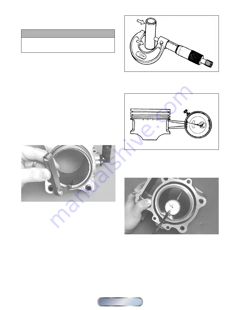
1. Measure the cylinder front to back in six places.
CC127D
2. Measure the corresponding piston diameter at a point
15 mm above the piston skirt at a right angle to the
piston-pin bore. Subtract this measurement from the
measurement in step 1. The difference (clearance)
must be within specifications.
Installing Piston Rings
1. Install ring expander (4) in the bottom groove of the
piston; then install the thin oil rings (3) over the
expander making sure the expander ends do not
overlap. Stagger the end gaps of the upper and lower
thin oil rings according to the illustration.
CAUTION
Improper cleaning of the ring-grooves by the use of
the wrong type of ring-groove cleaner will result in
severe damage to the piston.
Manual
Table of Contents


