


3-40
If tooth contact pattern is comparable to an incorrect
pattern, correct tooth contact according to the follow-
ing chart.
NOTE: To correct tooth contact, steps 1 and 2
(with NOTE) of “Correcting Backlash” must be fol-
lowed and the above “Tooth Contact/Shim Correc-
tion” chart must be consulted.
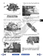
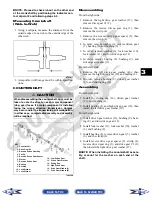
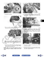
CRANKSHAFT ASSEMBLY
Measuring Connecting Rod
(Small End Inside Diameter)
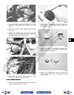
1. Insert a snap gauge into the upper connecting rod
small end bore; then remove the gauge and mea-
sure it with micrometer.
CC290D
2. Maximum diameter must not exceed specifica-
tions.
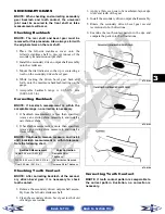
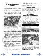
Measuring Connecting Rod
(Small End Deflection)
1. Place the crankshaft on a set of V-blocks and
mount a dial indicator and base on the surface
plate. Position the indicator contact point against
the center of the connecting rod small end journal.
2. Zero the indicator and push the small end of the
connecting rod away from the dial indicator.
3. Maximum deflection must not exceed specifica-
tions.
Measuring Connecting Rod
(Big End Side-to-Side)
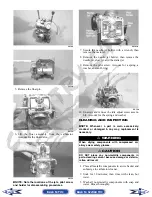
1. Push the lower end of the connecting rod to one
side of the crankshaft journal.
2. Using a feeler gauge, measure the gap between the
connecting rod and crankshaft journal.
CC289D
3. Acceptable gap range must be within specifica-
tions.
Measuring Connecting Rod
(Big End Width)
1. Using a calipers, measure the width of the con-
necting rod at the big-end bearing.
2. Acceptable width range must be within specifica-
tions.
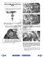
Measuring Crankshaft (Runout)
1. Place the crankshaft on a set of V blocks.
2. Mount a dial indicator and base on the surface
plate. Position the indicator contact at point 1 of
the crankshaft.
ATV-1074
3. Zero the indicator and rotate the crankshaft slowly.
4. Maximum runout must not exceed specifications.
Tooth Contact
Shim Correction
Contacts at Top
Decrease Shim Thickness
Contacts at Root
Increase Shim Thickness
! CAUTION
After correcting tooth contact, backlash must again
be checked and corrected (if necessary). Continue
the correcting backlash/correcting tooth contact
procedures until they are both within tolerance val-
ues.
! CAUTION
Care should be taken to support the connecting rod
when rotating the crankshaft.
Back to TOC
Back to Section TOC
Next
Back


