background image

4-2

Fuel/Lubrication/

Cooling

„

NOTE: Arctic Cat recommends the use of new

gaskets, lock nuts, and seals and lubricating all
internal components when servicing the
engine/transmission.

„

NOTE: Some photographs and illustrations used

in this section are used for clarity purposes only
and are not designed to depict actual conditions.

„

NOTE: Critical torque specifications are located

in Section 1.

Carburetor 

Specifications

(Prowler/XT)

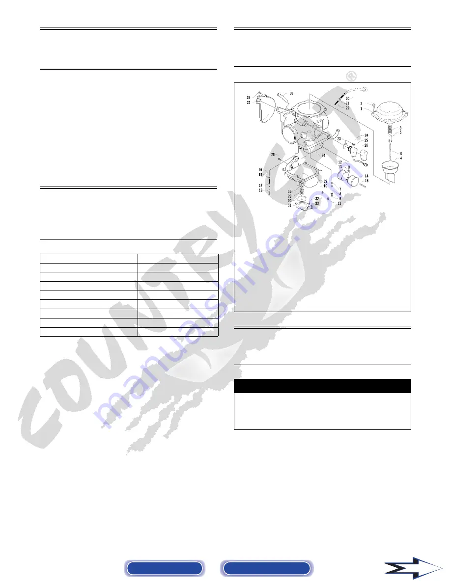
Carburetor Schematic

(Prowler/XT)

0741-115

Carburetor

(Prowler/XT)

REMOVING 

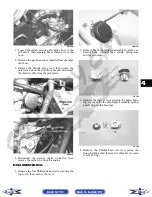
1. Remove the seats and center console; then remove

the left-side seat-base.

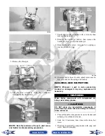
2. Loosen the clamps on the inlet boot; then remove

the boot from the left-side.

Type

Keihin CVK36

Main Jet

138

Slow Jet

40

Pilot Screw Setting (turns)

2

Needle Jet

6.0/4.0

Jet Needle

Fixed

Idle RPM

1250-1350

Starter Jet

85

Float Arm Height

17 mm (0.7 in.)

! WARNING

Whenever any maintenance or inspection is per-
formed on the fuel system during which there may
be fuel leakage, there should be no welding, smok-
ing, open flames, etc., in the area.

KEY

1. Cover

2. Screw

3. Spring

4. Vacuum Piston

5. Spring Seat

6. Jet Needle

7. Needle Jet

8. Jet Holder

9. Main Jet

10. Slow Jet

11. Starter Jet

12. Float Valve

13. Clip

14. Float Set

15. Float Pin

16. Pilot Screw

17. Spring

18. Washer

19. O-Ring

20. Idle Adjust Screw

21. Washer

22. Spring

23. Plate

24. Screw

25. Electric Choke

26. Choke Cover

27. Float Chamber 

Assy

28. Screw

29. Spring

30. Diaphragm Assy

31. Pump Housing

32. U-Ring

33. Screw

34. O-Ring

35. Screw

36. Screw

37. Cover

38. Vent Hose

Back to TOC

Back to Section TOC

Next

Содержание 2008 Prowler

Страница 1: ...emphasize important information The symbol WARNING identifies personal safety related information Be sure to fol low the directive because it deals with the possibility of severe personal injury or even death The symbol CAUTION identifies unsafe practices which may result in vehicle related damage Follow the directive because it deals with the possibility of damaging part or parts of the vehicle T...

Страница 2: ...GO ON TM UTV UTV TABLE OF CONTENTS Click on the red text to go Foreword 1 General Information Specifications 2 Periodic Maintenance Tune Up 3 Engine Transmission 4 Fuel Lubrication Cooling 5 Electrical System 6 Drive System 7 Suspension 8 Steering Frame 9 Controls Indicators 1 2 3 4 5 6 7 8 9 ...

Страница 3: ...neral Specifications 1 2 Torque Specifications 1 2 Torque Conversions ft lb N m 1 3 Tightening Torque General Bolts 1 3 Break In Procedure 1 4 Gasoline Oil Lubricant 1 4 Genuine Parts 1 5 Preparation For Storage 1 5 Preparation After Storage 1 6 Back to TOC ...

Страница 4: ...ft lb N m Engine Cradle Engine 40 54 Engine Cradle Rubber Mount 25 34 Front Differential Frame Differential Bracket 38 52 Rear Output Flange Rear U Joint Flange 40 54 Input Housing Differential Housing 23 31 Differential Housing Cover Differential Housing 23 31 Drive Bevel Gear Nut Shaft 87 118 Lock Collar Differential Housing 125 170 Hub Nut Front Rear Shaft Axle min 200 272 Oil Drain Plug Front ...

Страница 5: ...rive Pulley Clutch Shaft 165 224 Ground Wire Engine 8 11 Magneto Cover Crankcase 8 11 Oil Pump Drive Gear Crank Balancer Shaft 62 84 Output Shaft Flange Nut Output Shaft 62 84 Outer Magneto Cover Magneto Cover 8 11 Rotor Flywheel Nut Crankshaft 105 143 Cam Sprocket Camshaft 11 15 V Belt Cover Crankcase 8 11 ft lb N m ft lb N m ft lb N m ft lb N m 1 1 4 26 35 4 51 69 4 76 103 4 2 2 7 27 36 7 52 70 ...

Страница 6: ...enated gasolines containing up to 10 ethanol 5 methane or 5 MTBE are acceptable gasolines When using ethanol blended gasoline it is not neces sary to add a gasoline antifreeze since ethanol will pre vent the accumulation of moisture in the fuel system RECOMMENDED ENGINE TRANSMISSION OIL The recommended oil to use is Arctic Cat ACX All Weather synthetic engine oil which has been specifi cally formu...

Страница 7: ...ll the air filter and housing cover 4 On the carbureted models drain the carburetor float chamber 5 Plug the exhaust hole in the exhaust system with a clean cloth 6 Apply light oil to the plungers of the shock absorb ers 7 Tighten all nuts bolts cap screws and screws Make sure rivets holding components together are tight Replace all loose rivets Care must be taken that all calibrated nuts cap scre...

Страница 8: ...cables 7 Check the entire brake systems fluid level pads etc all controls headlights taillight brakelight and headlight aim adjust or replace as necessary 8 Tighten all nuts bolts cap screws and screws making sure all calibrated nuts cap screws and bolts are tightened to specifications 9 Check tire pressure Inflate to recommended pres sure as necessary 10 Make sure the steering moves freely and do...

Страница 9: ...nt Hoses 2 8 Adjusting Engine RPM Idle 2 8 Engine Transmission Oil Filter 2 9 Front Differential Rear Drive Differential Lubricant 2 10 Tires 2 10 Steering Components 2 11 Driveshaft Coupling 2 11 Suspension Shock Absorbers Bushings 2 11 Nuts Bolts Cap Screws 2 11 Ignition Timing 2 11 Headlight Taillight Brakelight 2 12 Switches 2 12 Shift Lever 2 13 Frame Welds 2 13 Electrical Connections 2 13 Hy...

Страница 10: ...edal Pivot I I C L A R Float Chamber Prowler XT D Engine RPM Idle Prowler XT I I A Engine Transmission Oil Level I A Engine Transmission Oil Filter R R R Oil Strainer I I C Front Differential Rear Drive Differ ential Lubricant I I R 4 Yrs Tires Air Pressure I I R Steering Components I I I R V Belt I l R Suspension Ball joint boots drive axle boots front and rear tie rods dif ferential and rear dri...

Страница 11: ...ning and main taining lead acid batteries Always read and follow instructions provided with battery chargers and battery products 1 Remove the battery hold down then disconnect the battery cables negative cable first 2 Disconnect the vent hose 3 Remove the battery from the vehicle then thor oughly wash the battery and battery compartment with soap and water NOTE If battery posts cable ends or the ...

Страница 12: ...el and the battery is ready for service 10 Place the battery in the battery compartment then coat the battery posts and cable ends with a light coat of multi purpose grease 11 Connect the battery cables positive cable first then install the battery hold down Fuses The main fuses are located in a power distribution module under the operator s seat If there is any type of electrical system failure a...

Страница 13: ... or debris from inside the air cleaner Be sure no dirt enters the carburetor Prowler XT 8 Place the filter assembly in the air filter housing making sure it is properly positioned and properly seated with the filter screen down PR090 9 Install the air filter housing cover and secure with the retaining clips then install the center console and seats making sure the seats lock securely CD670 CHECKIN...

Страница 14: ...ll the timing inspection plug 5 Place the two tappet covers with O rings into posi tion Tighten the cap screws securely Valve Tappet Clearance Valve Adjuster Procedure To check and adjust valve tappet clearance use the following procedure NOTE The engine must be cold for this proce dure NOTE The seats center console spark plug and air filter housing must be removed for this pro cedure 1 Remove the...

Страница 15: ...gine Compression To test engine compression use the following proce dure NOTE The engine must be warm and the battery must be fully charged for this test NOTE The seats and center console must be removed for this procedure 1 Remove the high tension lead from the spark plug 2 Using compressed air blow any debris from around the spark plug 3 Remove the spark plug then attach the high ten sion lead t...

Страница 16: ...d remove the spark arrester Account for a gasket PR498 PR499 2 Using a suitable brush clean the carbon deposits from the screen taking care not to damage the screen NOTE If the screen or gasket is damaged in any way it must be replaced 3 Install the spark arrester assembly and gasket and secure with the cap screws Tighten the cap screws to 48 in lb Gas Vent Hoses Replace the gas hose every two yea...

Страница 17: ...nd drain the oil into a drain pan PR078A 4 Using the Oil Filter Wrench and a ratchet handle or a socket or box end wrench remove the old oil filter NOTE Clean up any excess oil after removing the filter 5 Apply oil to a new filter O ring and check to make sure it is positioned correctly then install the new oil filter Tighten securely 6 Install the engine drain plug and tighten to 16 ft lb Pour th...

Страница 18: ...el plug 3 Drain the lubricant into a drain pan by removing in turn the drain plug from each ATV0082A PR530B 4 After all the lubricant has been drained install the drain plugs and tighten to 45 in lb 5 Pour the appropriate amount of recommended lubricant into the fill level hole 6 Install the fill level plugs NOTE If the lubricant is contaminated with water inspect the drain plug fill level plug an...

Страница 19: ...d broken or missing C Shock absorber body damaged punctured or leaking D Shock absorber eyelets broken bent or cracked E Shock absorber eyelet bushings worn deterio rated cracked or missing F Shock absorber spring broken or sagging G Sway bar mountings tight and bushings secure Nuts Bolts Cap Screws Tighten all nuts bolts and cap screws Make sure riv ets holding components together are tight Repla...

Страница 20: ...on the can opy support CHECKING ADJUSTING HEADLIGHT AIM The headlights can be adjusted vertically The geomet ric center of the HIGH beam light zone is to be used for vertical aiming 1 Position the vehicle on a level floor so the head lights are approximately 6 1 m 20 ft from an aiming surface wall or similar aiming surface NOTE There should be an average operating load on the vehicle when adjustin...

Страница 21: ...sher and a bushing PR461A 4 Turn the linkage rod clockwise or counterclock wise until the lower linkage hole aligns with the shift arm pin 5 Install the bushing and linkage and secure with the washer and E clip then tighten the jam nut securely Check each gear shift position for proper gear selection and make sure the proper icon illu minates on the LCD Frame Welds The frame and welds should be ch...

Страница 22: ...ult in air in the system D At this point perform steps B and C on the other FRONT bleeder screw then move to the REAR bleeder screw and follow the same pro cedure E Repeat steps B and C until the brake pedal is firm 4 Carefully check the entire hydraulic brake system that all hose connections are tight the bleed screws are tight the protective caps are installed and no leakage is present INSPECTIN...

Страница 23: ...intained to be fully functional 1 With the engine off transmission in neutral and the parking brake set attempt to move the vehicle 2 If the rear wheels are locked it is adjusted prop erly 3 If the rear wheels are not locked it must be adjusted set up ADJUSTING To adjust set up the parking brake use the following procedure NOTE Remove the four rear body screws secur ing the belly panel to the fram...

Страница 24: ...the caliper 4 Remove the anti rattle springs then push in on the caliper holder and remove the outer brake pad Remove the inner pad PR466A Inspecting and Measuring 1 Inspect the pads for gouges chips or wear 2 Inspect the disc for gouges grooves cracks and warpage 3 Using a calipers measure the thickness of each brake pad 4 If the thickness of either brake pad is less than 1 0 mm 0 039 in the brak...

Страница 25: ... cooling system use premixed Arctic Cat Antifreeze While the cooling system is being filled air pockets may develop therefore run the engine for five minutes after the initial fill shut the engine off and then fill the cooling system to the bot tom of the stand pipe in the radiator neck Checking Replacing V Belt REMOVING 1 Remove the seats and center console then remove the left side seat base PR1...

Страница 26: ...ap screw from the driven pulley face 3 Rotate the V belt and driven pulley clutch until the V belt is flush with the top of the driven pulley 4 Place the V belt cover gasket into position then install the cover and secure with the cap screws making sure the different lengthed cap screws are in their proper location Tighten the cap screws to 8 ft lb 5 Secure the seat base with the four cap screws T...

Страница 27: ...Bleed hydraulic system 5 Replace seal s Problem Brake pedal travel excessive Condition Remedy 1 Hydraulic system entrapped air 2 Brake fluid low 3 Brake fluid incorrect 4 Piston seal cup worn 1 Bleed hydraulic system 2 Add fluid to proper level 3 Replace with correct fluid 4 Replace seal cup Problem Brake fluid leaking Condition Remedy 1 Connection joints loose 2 Hose cracked 3 Piston seal worn 1 ...

Страница 28: ...3 1 3 SECTION 3 ENGINE TRANSMISSION TABLE OF CONTENTS Engine Transmission 3 2 Specifications 3 2 Prowler XT XTX Table of Contents 3 3 Troubleshooting 3 48 Back to TOC ...

Страница 29: ...ND GUIDES Valve Face Diameter intake exhaust 31 6 mm 1 24 in 27 9 mm 1 10 in Valve Tappet Clearance intake cold engine exhaust 0 1016 mm 0 004 in 0 1524 mm 0 006 in Valve Guide Stem intake exhaust Clearance 0 013 mm 0 0005 in Valve Guide Valve Stem max Deflection wobble method 0 35 mm 0 014 in Valve Guide Inside Diameter 5 000 5 012 mm 0 1969 0 1973 in Valve Stem Outside intake exhaust Diameter 4 ...

Страница 30: ...122A CYLINDER PISTON AND RINGS Piston Skirt Cylinder Clearance 0 045 mm 0 0018 in Piston Diameter 15 mm 0 6 in from Skirt End Prowler XT 97 948 97 962 mm 3 856 3 857 in Piston Diameter 12 mm 0 47 in from Skirt End XTX 101 930 101 949 mm 4 013 4 014 in Piston Ring Free End Gap 1st 2nd 12 5 mm 0 492 in Bore x Stroke Prowler XT 97 9 x 85 mm 3 86 x 3 35 in Bore x Stroke XTX 102 x 82 mm 4 01 x 3 22 in ...

Страница 31: ...uel level sensor con nector XT XTX and reverse override switch connector PR130A PR155C PR157A 5 From the left side disconnect the starter wire alternator connector CDI connector Prowler XT gear shift position switch and electric choke con nector then remove the cap screw securing the main harness ground and the battery ground wires to the starter PR145A PR128A PR474B Back to TOC Back to Section TO...

Страница 32: ...using boot then remove the crankcase breather hose from the crankcase PR127A PR118 9 Remove four self tapping screws securing the air filter mounting bracket to the frame then remove the air filter and mounting bracket as an assembly PR140A 10 Remove the throttle arm cover from the carbure tor throttle body then disconnect and remove the throttle cable and the carburetor throttle body PR154A 11 Re...

Страница 33: ...drive coupler and three on the rear drive coupler securing the driveshafts to the drive couplers NOTE Remove the front driveshaft first or the parking brake will not hold the coupler stationary and cap screw removing will be more difficult PR152A PR120A 15 Separate the drive coupler flanges then remove the driveshafts from the splined slip joints being careful not to damage the rubber boots The fr...

Страница 34: ...ot have to removed from the frame for this procedure Removing Top Side Components A Valve Cover B Cylinder Head NOTE Remove the spark plug and timing inspec tion plug then using an appropriate wrench rotate the crankshaft to top dead center of the compres sion stroke 1 Remove the two tappet covers CC001D NOTE Keep the mounting hardware with the cov ers for assembly purposes or thread them back int...

Страница 35: ...ad then remove the C ring NOTE Care should be taken not to drop the C ring down into the crankcase CC012D 5 Bend the washer tabs down and remove the two cap screws securing the sprocket to the camshaft then drop the sprocket off the camshaft CC013D 6 Remove the cap screw securing the chain ten sioner account for a washer then remove the ten sioner CC014D 7 While holding the chain slide the sprocke...

Страница 36: ...ocation of the dif ferent sized cap screws and nuts CC017D CC018D CC016D 9 Remove the cylinder head from the cylinder remove the gasket and account for two alignment pins then remove the cam chain guide CC020D CC022D AT THIS POINT To service valves and cylinder head see Servicing Top Side Components sub section AT THIS POINT To inspect cam chain guide see Servicing Top Side Components sub section ...

Страница 37: ...Account for the gasket and two alignment pins CC024D CC025D CC026D 13 Using an awl remove one piston pin circlip CC032D 14 Using the Piston Pin Puller remove the piston pin Account for the opposite side circlip Remove the piston NOTE It is advisable to remove the opposite side circlip prior to using the puller CC033D AT THIS POINT To service cylinder see Servicing Top Side Compo nents sub section ...

Страница 38: ...e move the valve cover in a figure eight motion Inspect the sealing surface for any indica tion of high spots A high spot can be noted by a bright metallic finish Correct any high spots before assembly by continuing to move the valve cover in a figure eight motion until a uniform bright metallic finish is attained CC130D Removing Valves NOTE Keep all valves and valve components as a set Note the o...

Страница 39: ...ons Measuring Valve Face Seat Width 1 Using a micrometer measure the width of the valve face ATV 1004 2 Acceptable width range must be within specifica tions Measuring Valve Face Radial Runout 1 Mount a dial indicator on the surface plate then place the valve stem on a set of V blocks 2 Position the dial indicator contact point on the out side edge of the valve face then zero the indicator ATV1082...

Страница 40: ...ifications Measuring Rocker Arm Shaft Outside Diameter 1 Using a micrometer measure the outside diameter of the rocker arm shaft 2 Acceptable outside diameter range must be within specifications Installing Valves 1 Apply grease to the inside surface of the valve seals then place a lower spring seat and valve guide seal over each valve guide CC144D 2 Insert each valve into its original location 3 I...

Страница 41: ...tion When installing new rings install as a complete set only Cleaning Inspecting Piston Rings 1 Take an old piston ring and snap it into two pieces then grind the end of the old ring to a 45 angle and to a sharp edge 2 Using the sharpened ring as a tool clean carbon from the ring grooves Be sure to position the ring with its tapered side up Measuring Piston Ring End Gap Installed 1 Place each com...

Страница 42: ... If the cylinder cylinder head assembly cannot be trued they must be replaced Cleaning Inspecting Cylinder Head 1 Using a non metallic carbon removal tool remove any carbon buildup from the combustion chamber being careful not to nick scrape or damage the combustion chamber or the sealing surface 2 Inspect the spark plug hole for any damaged threads Repair damaged threads using a heli coil insert ...

Страница 43: ...spots before assembly by continuing to move the cylin der in a figure eight motion until a uniform bright metallic finish is attained CC129D Inspecting Cam Chain Guide 1 Inspect cam chain guide for cuts tears breaks or chips 2 If the chain guide is damaged it must be replaced Honing Cylinder 1 Using a slide gauge and a dial indicator or a snap gauge measure the cylinder bore diameter in three loca...

Страница 44: ...mshaft and note runout maximum tolerance must not exceed specifications Measuring Camshaft Lobe Height 1 Using a calipers measure each cam lobe height ATV1013A 2 The lobe heights must not exceed minimum speci fications Inspecting Camshaft Bearing Journal 1 Inspect the bearing journal for scoring seizure marks or pitting 2 If excessive scoring seizure marks or pitting is found the cylinder head ass...

Страница 45: ...e Pin 1 Inspect the spring and drive pin for damage CF061A CF060A 2 If damaged the camshaft must be replaced Installing Top Side Components A Piston B Cylinder 0732 301 NOTE If the piston rings were removed install them in this sequence A Install ring expander 4 in the bottom groove of the piston then install the thin oil rings 3 over the expander making sure the expander ends do not overlap Stagg...

Страница 46: ... the arrow points toward the exhaust CC032D 2 Place the two alignment pins into position Place the cylinder gasket into position then place a pis ton holder or suitable substitute beneath the pis ton skirt and square the piston in respect to the crankcase CC025D 3 Lubricate the inside wall of the cylinder then using a ring compressor or the fingers compress the rings and slide the cylinder over th...

Страница 47: ...ug CC272D 9 Loosely install the five cylinder head nuts 10 In a crisscross pattern tighten the four cylinder head cap screws from step 8 to 40 ft lb then tighten the 8 mm nut from step 9 to 18 ft lb Using a crisscross pattern tighten the 6 mm nuts from step 9 to 8 ft lb Tighten the two cylin der to crankcase nuts from step 4 securely 11 With the timing inspection plug removed and the chain held ti...

Страница 48: ...ition CD463 15 Seat the cam sprocket onto the camshaft making sure the alignment pin in the camshaft aligns with the smallest hole in the sprocket then place the camshaft sprocket assembly onto the cylinder ensuring the following CF013A A Piston still at top dead center B Camshaft lobes directed down toward the pis ton C Camshaft alignment marks parallel to the valve cover mating surface D Recesse...

Страница 49: ...o 11 ft lb Bend the tab to secure the cap screw CD466 20 Place the C ring into position in its groove in the cylinder head CC012D 21 Install the cylinder head plug in the cylinder head with the open end facing downward and toward the inside CD468 22 Remove the cap screw from the end of the chain tensioner then using a flat blade screwdriver rotate the adjuster screw inside the tensioner clockwise ...

Страница 50: ...n coat of Three Bond Sealant to the mating surfaces of the cylinder head and valve cover CC275D 27 Place the valve cover into position NOTE At this point the rocker arms and adjuster screws must not have pressure on them 28 Install the four top side cap screws with rubber washers then install the remaining cap screws Tighten only until snug CC003D 29 In a crisscross pattern starting from the cente...

Страница 51: ...ount for the gasket 2 Remove the flange nut securing the spacer to the crankshaft then remove the spacer Account for the O ring PR465 3 Using a cold chisel scribe a mark showing the rel ative position of the shift arm to the shift arm shaft to aid in installing then remove the shift arm PR429A 4 Remove the two cap screws securing the speed sensor housing then remove the housing Account for the gas...

Страница 52: ...y shaft washers that may have come off with the cover Make sure they are returned to their respective shafts and that the starter idler gear spacer is on the shaft or in the cover see Section 4 CF075A 9 Remove the nut securing the magneto rotor to the crankshaft then install the magneto rotor puller adapter NOTE The puller has left hand threads 10 Using Magneto Rotor Remover Set remove the rotor f...

Страница 53: ...g the driven gear and drive gear Failure to do so could result in the loss of an alignment pin into the crankcase 14 Remove the shift shaft noting the timing marks for assembling purposes Account for two washers PR430A 15 Remove the gear shift cam plate then remove the cam stopper and cam stopper spring Account for two washers PR434A Installing Right Side Components NOTE Plug the oil passage in th...

Страница 54: ...he snap ring should be facing outward NOTE Once the gears are secured remove the oil passage plug from the crankcase 3 Install the two starter gear shafts then install the two starter gears with the beveled side of the intermediate gear facing inward as noted in removing CD139 PR447A 4 In order on the crankshaft install a washer ring gear key and the magneto rotor Secure with the nut threads coate...

Страница 55: ...on the mounting stud with red Loctite 271 and install the nut Tighten securely PR434A 7 Install the shift shaft with two washers making sure to align the timing mark on the shift shaft with the mark on the shift cam plate CD954A CD927A 8 Lubricate the magneto cover gasket with fresh engine oil then place it into position on the two alignment pins Make sure the outer shift shaft washer is in place ...

Страница 56: ...sition on the right side cover then tighten four screws to 8 ft lb Left Side Components NOTE For efficiency it is preferable to remove and disassemble only those components which need to be addressed and to service only those components The technician should use discretion and sound judgment NOTE The engine transmission does not have to be removed from the frame for this procedure Removing Left Si...

Страница 57: ...rews securing the clutch cover Note the location of the different lengthed cap screws for installing purposes Using a rubber mal let carefully remove the cover Account for two alignment pins CD973A CD974A NOTE For steps 7 13 refer to illustration CC829B NOTE To aid in installing it is recommended that the assemblies are kept together and IN ORDER CAUTION Care must be taken when removing the cover ...

Страница 58: ...e clutch hous ing seal CF088A 9 Remove the two Allen head screws securing the gear shift position switch then remove the sensor Account for two neutral contact pins and two springs CD997 10 Remove the nut left hand threads securing the clutch shoe assembly C FI279A 11 Remove the cap screw securing the oil pump drive gear B Account for a cap screw washer pin and spacer KEY A Oil Pump Driven Gear B ...

Страница 59: ...ng the oil pump driven gear A then remove the gear noting the direction of the sides of the gear for installing pur poses Account for a pin and a washer CD984 CD895A 14 Remove the cap screws securing the oil pump then remove the pump CD988 Servicing Left Side Components NOTE Whenever a part is worn excessively cracked damaged in any way or out of tolerance replacement is necessary Back to TOC Back...

Страница 60: ...ection 3 If the inner race is locked in place or rotates both directions the drive assembly must be replaced INSPECTING OIL PUMP 1 Inspect the pump for damage 2 It is inadvisable to remove the screw securing the pump halves If the oil pump is damaged it must be replaced CD988A DRIVEN PULLEY NOTE The driven pulley is a non serviceable component If pulley faces cam ramps or sheave bushings are worn ...

Страница 61: ...ar is facing toward the inside Secure the gear with the cap screw threads coated with red Loctite 271 and the washer Tighten the cap screw to 62 ft lb CD992 CD991 5 Grease the driven gear pin and insert it into the oil pump shaft then install the driven gear noting the direction of the sides of the gear from removing Secure with a snap ring CD985A CD984 NOTE When installed correctly the sides of t...

Страница 62: ...lutch cover clutch housing assembly into position on the crankcase then secure with the cap screws making sure the different lengthed cap screws are in their proper location Tighten to 8 ft lb 12 Place the air intake plate cushion into position then install the air intake plate Tighten the cap screws threads treated with a small amount of red Loctite 271 securely CD971 CD970 13 Place the driven pu...

Страница 63: ... lb CD083 Center Crankcase Components NOTE This procedure cannot be done with the engine transmission in the frame Complete Removing procedures for Top Side Left Side and Right Side must precede this procedure NOTE For efficiency it is preferable to remove and disassemble only those components which need to be addressed and to service only those components The technician should use discretion and ...

Страница 64: ... forks taking note of the direction of the tabs on the forks for assembling purposes 4 Remove the gear shift shaft G noting the location of the two holes on the end of the shaft Account for two washers PR380A 5 Remove the countershaft assembly D Account for a washer on each end of the countershaft CC674 NOTE Do not disassemble the countershaft assembly unless necessary If necessary see Ser vicing ...

Страница 65: ...eads 11 Remove the cap screws securing the oil strainer cap then remove the cap 12 Remove the two cap screws securing the oil strainer then remove the strainer PR406 13 To remove the assembly remove the nut securing the secondary drive gear and secondary driven gear then from the inside of the crankcase using a rubber mallet remove the output shaft assembly Account for the output shaft two gears a...

Страница 66: ...shim 2 If backlash measurement is more than specified remove an existing shim measure it and install a thicker shim NOTE Continue to remove measure and install until backlash measurement is within tolerance Note the following chart Checking Tooth Contact NOTE After correcting backlash of the second ary driven bevel gear it is necessary to check tooth contact 1 Remove the secondary driven output sh...

Страница 67: ... to Side 1 Push the lower end of the connecting rod to one side of the crankshaft journal 2 Using a feeler gauge measure the gap between the connecting rod and crankshaft journal CC289D 3 Acceptable gap range must be within specifica tions Measuring Connecting Rod Big End Width 1 Using a calipers measure the width of the con necting rod at the big end bearing 2 Acceptable width range must be withi...

Страница 68: ...dog 14 driven gear washer 13 and bushing 9 2 Install bearing 8 and high driven gear 15 then install the left drive gear washer 16 From the right side 1 Install driven gear washer 13 bushing 9 bear ing 8 and low driven gear 12 2 Install lock washer 11 lock washer 10 washer 6 and bushing 9 3 Install bearing 8 reverse driven gear 7 washer 6 and the circlip 4 4 Install reverse driven gear spacer 5 cir...

Страница 69: ...bearing until the oil begins to smoke then slide the crankshaft assembly into place CC688 CC689 NOTE If heating the bearing is not possible the crankshaft can be installed using a crankshaft installing tool 4 Install the crank balancer CD832B NOTE It will be necessary to rotate the crank bal ancer until the counterweight is facing away from the crankshaft then rotate the crankshaft clock wise into...

Страница 70: ...ork tabs face upward and that they are properly seated into the shift cams CC669 10 Install the reverse idler gear assembly noting the positioning of the two washers gear bushing and shaft CC668 11 Install the front and rear secondary driven shaft assemblies into the left side of the crankcase mak ing sure the bearing locating pins are facing upward and the bearing C ring is fully seated in the cr...

Страница 71: ... steps 5 6 until the halves are correctly joined then tighten to 20 ft lb NOTE Rotate the shafts back and forth to ensure no binding or sticking occurs 10 In a crisscross case to case pattern tighten the 6 mm cap screws from steps 7 8 to 8 ft lb NOTE Rotate the shafts back and forth to ensure no binding or sticking occurs Installing Engine Transmission NOTE Arctic Cat recommends that new gaskets a...

Страница 72: ... marks and slide the splines into the slip joints PR148 PR151A 5 Install the cap screws securing the drive line cou plers to the drive flanges and tighten to 40 ft lb PR120A 6 Set the exhaust pipe in place then install the muf fler and align the assembly to the engine Install two cap screws securing the exhaust pipe to the cylinder head and tighten to 20 ft lb 7 Install the inlet boot on the V bel...

Страница 73: ...onnector Prowler XT alternator connector gear shift position switch and electric choke connector PR145A PR128A 10 From the left side connect the speed sensor con nector XT XTX fuel level sensor connector XT XTX and temperature sensor lead then install the spark plug cap PR155B PR130A NOTE Make sure the main harness ground and battery ground wires are installed and secured in the proper location wi...

Страница 74: ...er linkage to the transmission shift arm placing the washer and bushing in appro priate locations then secure with the E clip NOTE Before operating vehicle check and adjust shifter linkage as required see Section 2 15 Fill the engine transmission with the appropriate lubricant 16 Fill the cooling system with the appropriate cool ant 17 Connect the positive battery cable to the battery then connect...

Страница 75: ...tor float valve defective Prowler XT 3 Fuel hose obstructed 4 Fuel screens obstructed 5 Fuel pump defective 1 Clean vent hose 2 Replace valve 3 Clean replace hose 4 Clean replace inlet screen valve screen 5 Replace fuel pump Problem Engine stalls easily Condition Remedy 1 Spark plug fouled 2 Magneto defective 3 CDI unit ECU defective 4 Carburetor jets fuel injector obstructed 5 Valve clearance out...

Страница 76: ...ome from secondary bevel gear and final driven shaft Condition Remedy 1 Drive driven bevel gears damaged worn 2 Backlash excessive 3 Tooth contact improper 4 Bearing damaged 5 Gears worn rubbing 6 Splines worn 7 Final driven shaft thrust clearance too large 1 Replace gears 2 Adjust backlash 3 Adjust contact 4 Replace bearing 5 Replace gears 6 Replace shaft s 7 Replace thrust washer s Problem Engin...

Страница 77: ...fts worn 8 Spark plug gap incorrect 9 Carburetor jets fuel injector obstructed 10 Float level out of adjustment Prowler XT 11 Air cleaner element obstructed 12 Oil in the engine overfilled contaminated 13 Intake manifold leaking air 14 Cam chain worn 1 Adjust clearance 2 Replace springs 3 Time camshaft 4 Replace service rings cylinder 5 Repair seats 6 Clean replace plug 7 Replace arms shafts 8 Adj...

Страница 78: ...onic Fuel Injection XTX 4 6 Engine RPM Idle Prowler XT 4 8 Gas Tank 4 8 Gas Vent Hoses 4 11 Oil Filter Oil Pump 4 11 Oil Cooler XTX 4 12 Liquid Cooling System 4 12 Radiator 4 13 Thermostat 4 14 Fan 4 15 Water Pump 4 15 Electric Fuel Pump Fuel Level Sensor XTX 4 16 Vacuum Pulse Fuel Pump Prowler XT 4 18 Fuel Level Sensor XT 4 18 Troubleshooting Prowler XT 4 20 Troubleshooting XTX 4 20 Back to TOC ...

Страница 79: ...Keihin CVK36 Main Jet 138 Slow Jet 40 Pilot Screw Setting turns 2 Needle Jet 6 0 4 0 Jet Needle Fixed Idle RPM 1250 1350 Starter Jet 85 Float Arm Height 17 mm 0 7 in WARNING Whenever any maintenance or inspection is per formed on the fuel system during which there may be fuel leakage there should be no welding smok ing open flames etc in the area KEY 1 Cover 2 Screw 3 Spring 4 Vacuum Piston 5 Spri...

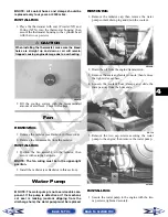
Страница 80: ...hoke connector then remove the carburetor from the engine DISASSEMBLING 1 Remove the four Phillips head screws securing the top cover then remove the cover CH015D 2 Remove the vacuum piston assembly from the car buretor body Account for a spring spring seat and the jet needle CC746 3 Remove the three screws securing the pump hous ing Account for the diaphragm assembly spring and U ring in the hous...

Страница 81: ... Unscrew and remove the idle adjust screw assem bly Account for the spring and washer CLEANING AND INSPECTING NOTE Whenever a part is worn excessively cracked or damaged in any way replacement is necessary 1 Place all metallic components in a wire basket and submerge in carburetor cleaner 2 Soak for 30 minutes then rinse with clean hot water 3 Wash all non metallic components with soap and water R...

Страница 82: ...the washer and spring are properly positioned 2 Install the pilot screw with the spring the washer and the O ring in this order CC758 NOTE Turn the pilot screw clockwise until it is lightly seated then turn it counterclockwise the recommended number of turns as an initial set ting NOTE Note the locations of the jets and holder during assembling procedures CC761A 3 Install the slow jet Tighten secu...

Страница 83: ...uretor into the intake boot and tighten the clamp securely 5 Install the inlet boot between the air filter housing and the carburetor then tighten the clamps securely 6 Install the left side seat base then install the cen ter console and the seats making sure the seats lock securely Electronic Fuel Injection XTX CAUTION It is important to press down on the pump housing until it contacts the carbur...

Страница 84: ...Remove the connector from the IAT sensor A then loosen the inlet boot clamp B and remove the mounting screw C PR486A 4 Disconnect the crankcase breather hose from the air filter housing then remove the air filter assem bly from the vehicle PR487A 5 Slowly disconnect the gasline hose connector from the fuel rail FI092A 6 Remove the screw securing the throttle actuator cover to the throttle body the...

Страница 85: ...wler XT To adjust idle RPM see Section 2 Gas Tank REMOVING 1 Remove the seats and center console then remove the left side and right side seat bases 2 Remove twelve cap screws and two self tapping screws securing the floorboard to the frame 3 While pulling forward on the upper portion of the floorboard lift the rear panel above the seat lock studs then insert a small wood block to hold in position...

Страница 86: ...ank hold down strap then remove the inside hold down strap PR172A 9 Lift and slide the tank forward raising the front of the tank first then turn the tank and lift out the right side CLEANING AND INSPECTING NOTE Whenever a part is worn excessively cracked or damaged in any way replacement is necessary 1 Clean all gas tank components with parts cleaning solvent 2 Inspect all hoses for cracks or lea...

Страница 87: ...his time PR166A 4 Place the gas cap filler panel into position then if necessary position the gas tank so the filler panel and filler neck are not binding or rubbing PR176 5 Secure the filler panel with four press nuts then tighten the hardware securing the hold down straps from steps 2 3 securely PR166A PR167A WARNING Whenever any maintenance or inspection is made on the fuel system during which ...

Страница 88: ...ay occur when install ing the oil pressure gauge Wipe up oil residue with a cloth 4 Set the parking brake and start the engine Allow the engine to warm up to operating temperature with cooling fan cycling 5 Set the speedometer tachometer to RPM XT XTX or connect a suitable tachometer Prowler With the engine running at 2500 RPM the pressure gauge must show 0 7 0 8 kg cm 10 20 psi 6 Install the left...

Страница 89: ... INSPECTING NOTE Whenever a part is worn excessively cracked or damaged in any way replacement is necessary 1 Prior to washing inspect the oil cooler for signs of leaks such as oily dirt build up 2 Wash the cooling fins using a pressure washer or hot soapy water and a soft brush 3 Inspect all mounting brackets and the oil inlet and outlet for cracks or bends INSTALLING 1 Place the oil cooler into ...

Страница 90: ...unt and remove the storage box PR186 4 Drain the coolant into a suitable container then disconnect the cooling fan wire connector from the main harness PR183A 5 Remove the two shoulder bolts and nuts securing the radiator to the frame then disconnect the upper and lower coolant hoses PR184A 6 Lift the radiator assembly from the vehicle Account for two upper and two lower rubber mounting grommets C...

Страница 91: ...e 6 Start the engine and warm up to operating temper ature then check that the coolant level is at the specified level see Section 2 Add coolant as nec essary Thermostat REMOVING 1 Drain approximately one quart of coolant from the cooling system 2 Remove the two cap screws securing the thermo stat housing to the cylinder head Account for a thermostat with seal Prowler XT and O ring XTX INSPECTING ...

Страница 92: ...he water pump is not a serviceable com ponent If the pump is defective or if the mechani cal seal is leaking coolant dripping from the discharge hole the water pump must be replaced REMOVING 1 Remove the radiator cap then remove the water pump coolant drain plug and drain the coolant PR122A 2 Drain the oil from the engine transmission 3 Remove the seats and center console then remove the right sid...

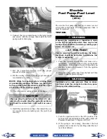
Страница 93: ...sure If the sound is heard 10 seconds no electrical checks are necessary Turn the ignition switch OFF 2 Disconnect the gasline hose from the fuel rail then install a suitable pressure gauge FI092A 3 Turn the ignition switch to the ON position The fuel pressure should build until the pump shuts off Pressure should read 3 0 kg cm2 43 psi 4 If the pump is not running disconnect the fuel pump sensor c...

Страница 94: ...r and resistor with clean alcohol and retest If still not correct replace the fuel level sensor 4 To replace the fuel level sensor use the following procedure A Disconnect the two wire connector A then press the fuel level sensor toward the top of the fuel pump to release it from the mounting slot B FI460A B Engage the tabs C of the fuel level sensor into the mounting slot B and press toward the b...

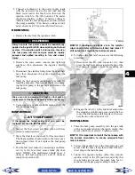
Страница 95: ...the fuel pump to the electrical tray then remove the pump INSTALLING 1 Place the fuel pump into position on the electrical tray then secure with the machine screws and flange nuts Tighten securely 2 Connect two gas hoses and one vacuum hose then secure with the clamps Fuel Level Sensor XT REMOVING 1 Remove the seats and the center console then remove the right side seat base 2 Remove the gasline h...

Страница 96: ...ms at the empty fuel posi tion D ATV2116 NOTE If readings are erratic clean the resistor wiper and resistor with a clean cloth soaked with alcohol and retest If the readings shown are not as specified replace the fuel level sensor assem bly INSTALLING 1 Using a new seal place the fuel level sensor into position in the gas tank then secure the fuel level sensor mounting plate Tighten the four torx ...

Страница 97: ...rly 5 Filter obstructed 6 Float height incorrect 1 Shift into higher gear decrease RPM speed 2 Clean main jet 3 Clean needle jet 4 Check piston operation 5 Clean filter 6 Adjust float height Problem Overflow and fuel level fluctuations Condition Remedy 1 Float valve worn damaged 2 Float valve spring broken 3 Float not working properly 4 Float valve dirty 5 Float height too high too low 1 Replace v...

Страница 98: ...ts XTX 5 7 Speed Sensor XT XTX 5 7 Ignition Switch 5 8 Headlight Switch 5 8 2WD 4WD Selector Switch 5 8 Differential Lock Switch 5 8 Reverse Override Switch 5 9 Front Drive Actuator 5 9 Stator Coils Prowler XT 5 10 Stator Coil Crankshaft Position CKP Sensor XTX 5 11 Starter Motor 5 12 Starter Relay 5 12 CDI Unit Prowler XT 5 13 Electronic Control Unit ECU XTX 5 13 Regulator Rectifier 5 13 Neutral ...

Страница 99: ...high tension plug cap removed to ground Ignition Coil Peak primary CDI Voltage 142 4 213 6 DC volts blue white to ground Stator Coil Resistance trigger charging signal 160 240 ohms green to blue Less than 1 ohm black to black Less than 1 ohm yellow to white Peak Voltage trigger signal 4 2 6 3 volts green to blue 0 4 0 6 volts yellow to white Charging Coil Output no load 60 AC volts 5000 RPM black ...

Страница 100: ...r the positive connector then connect the black tester lead to ground 3 The meter must show battery voltage NOTE If the meter shows no battery voltage troubleshoot the battery fuse receptacle connec tor or the main wiring harness Brakelight Switch The switch connector is the two prong black connector below the master cylinder NOTE The ignition switch must be in the ON position VOLTAGE Wiring Harne...

Страница 101: ...low the oil to cool and when the temperature is within a temperature range of 67 82 C 150 184 F the meter should show an open circuit 7 If the readings are not as indicated the switch must be replaced 8 Install the switch and tighten securely 9 Connect the switch leads Engine Coolant Temperature ECT Sensor XTX 1 Connect the meter leads selector in OHMS posi tion to the sensor terminals 2 Suspend t...

Страница 102: ...ibution module under the operator s seat If there is any type of electrical system failure always check the fuses first 1 Remove all fuses from the power distribution module 2 Set the meter selector to the DC Voltage position 3 Connect the black tester lead to ground 4 Using the red tester lead contact each end of the fuse holder connector terminals individually 5 The meter must show battery volta...

Страница 103: ...en connect the black tester lead to the other end of the cap AR603D 2 The meter reading must be within specification NOTE If the meter does not show as specified replace the spark plug cap PEAK VOLTAGE NOTE All of the peak voltage tests should be made using the Fluke Model 73 Multimeter with Peak Voltage Reading Adapter If any other type of tester is used readings may vary due to internal circuitr...

Страница 104: ...s specified replace the sensor Speed Sensor XT XTX NOTE Prior to testing the speed sensor inspect the three wire connector on the speed sensor for contamination broken pins and or corrosion 1 Set the meter selector to the DC Voltage position 2 With appropriate needle adapters on the meter leads connect the red tester lead to the voltage lead V then connect the black tester lead to the ground lead ...

Страница 105: ...oubleshoot the LIGHTS fuse on the power distribution module the ignition switch or the main harness 3 Connect the red meter lead to the yellow wire then select the high beam position on the headlight switch The meter must show battery voltage 4 Connect the red meter lead to either of the two white wires then select the low beam position on the headlight switch The meter must show battery voltage N...

Страница 106: ...meter showing should not change from step 1 3 Select 4WD on the 2WD 4WD selector switch The meter must show approximately 5 DC volts 4 Depress the reverse override switch The meter must show approximately 1 5 DC volts 5 Connect the red meter lead to the red yellow wire The meter must show approximately 1 5 DC volts Depress the reverse override switch The meter must show approximately 1 5 DC volts ...

Страница 107: ... on the meter must show 14 15 5 DC volts NOTE If voltage is lower than specified test Charging Coil No Load VOLTAGE Charging Coil No Load The connector is the three wire one on the left side of the engine just above the centrifugal clutch housing NOTE Test the connector that comes from the engine 1 Set the meter selector to the AC Voltage position 2 Test between the three black wires for a total o...

Страница 108: ...in one on the left side above the shift lever FI083B NOTE Test the connector that comes from the engine 1 Set the meter selector to the AC Voltage position 2 Test between the three yellow wires for a total of three tests 3 With the engine running at a constant 5000 RPM all wire tests must be within specifications NOTE If both stator coil tests failed check all connections etc and test again If no ...

Страница 109: ...ot away NOTE The ignition switch must be in the ON posi tion and the shift lever in the NEUTRAL position 1 Set the meter selector to the DC Voltage position 2 Connect the red tester lead to the starter terminal then connect the black tester lead to ground 3 With the starter button depressed the meter must show battery voltage and the starter motor should operate AR607D NOTE If the meter showed bat...

Страница 110: ...ed beneath the seat near the battery NOTE The ECU is not a serviceable component If the unit is defective it must be replaced The ECU is rarely the cause for electrical problems however if the ECU is suspected substitute another ECU to verify the suspected one is defective This EFI system has a built in feature that will only allow an ECU of the same part number to be used in this model Do not att...

Страница 111: ...onnect the black tester lead to the black wire then connect the red tester lead to the white wire The meter should show battery voltage 3 With the ignition key in the LIGHTS position the meter must show battery voltage NOTE If battery voltage is not shown and the headlights are illuminated inspect the three wire connector in the left rear canopy tube at the junc ture of the canopy tube and lower f...

Страница 112: ...n switch to the ON position 2 After ten seconds release the reverse override switch and turn the ignition switch to the OFF position then turn the ignition switch to the ON position The display should read EC00 no fault detected NOTE If the LCD still displays an error code continue troubleshooting the appropriate compo nent 3 Disconnect the diagnostic harness then install the black rubber cap 4 In...

Страница 113: ...ead to the black yellow wire A then turn the ignition switch ON and observe the meter The meter should read 0 8 3 0 DC volts CD705B 4 Tilt the sensor 60 or more to the left and right observing the meter The meter should read 4 0 8 0 DC volts after approximately one second in the tilted position If the meter readings are not as specified the tilt sensor is defective CD709 NOTE When replacing the se...

Страница 114: ...gative lead 8 Connect the main harness TPS connector to the TPS then using MaxiClips connect the black tester lead to the black wire and the red tester lead to the black wire PR546A 9 Select the DC Voltage position on the meter and turn the ignition switch to the ON position The meter should read approximately 0 6 DC volts with the throttle closed and approximately 5 0 DC volts with the throttle i...

Страница 115: ...nostic connector under the seat next to the PDM then install the test plug from Test Plug Error Code List onto the connector 4 Turn the ignition switch to the ON position and note the position of the TPS indicator icon A B or C then adjust the TPS until the TPS icon appears in the center position B PR542A PR540A PR541A 5 Tighten the mounting screws securely then verify the TPS icon appears in the ...

Страница 116: ... electrodes overheat or burn Condition Remedy 1 Spark plug incorrect too hot 2 Engine overheats 3 Spark plug loose 4 Mixture too lean Prowler XT 1 Replace plug 2 Service cooling system 3 Tighten plug 4 Adjust carburetor Problem Battery does not charge Condition Remedy 1 Lead wires connections shorted loose open 2 Magneto coils shorted grounded open 3 Regulator rectifier shorted punctured 1 Repair ...

Страница 117: ...ttery sulfation Acidic white powdery substance or spots on surfaces of cell plates Condition Remedy 1 Charging rate too low too high 2 Battery electrolyte excessive insufficient 3 Specific gravity too high too low 4 Battery run down damaged 5 Electrolyte contaminated 1 Replace battery 2 Keep electrolyte to prescribed level 3 Charge battery add distilled water 4 Replace battery 5 Replace battery Pr...

Страница 118: ...F CONTENTS Drive System 6 2 Front Drive Actuator 6 2 Front Differential 6 3 Drive Axles 6 15 Rear Gear Case Prowler XT Rear Differential XTX 6 20 Hub 6 21 Hydraulic Brake Caliper 6 23 Universal Joints 6 24 Troubleshooting 6 27 Back to TOC ...

Страница 119: ...r is located on the right side of the front drive input housing With the engine stopped and the ignition switch in the ON position a momen tary whirring sound can be heard each time the front drive selector switch is shifted If no sound is heard see Section 5 If the actuator runs constantly or makes squealing or grinding sounds the actuator must be replaced REMOVING 1 Select 4WD on the front drive...

Страница 120: ...ting of the actuator 5 Tighten the remaining cap screws then connect the electrical plug to the main harness 6 Turn the ignition switch to the ON position and check the operation by shifting the selector switch several times 7 Secure the wiring harness to the frame with a nylon cable tie then install the inner fender panel Front Differential REMOVING 1 Remove the belly panel then place the vehicle...

Страница 121: ... connec tor from the main harness then disconnect the dif ferential lock indicator connector from the differential lock switch located on the right side of the differential PR191 9 Remove two cap screws securing the differential lock cable support then disconnect the differential lock cable at the differential PR194A PR195A 10 Remove the lower and upper ball joint cap screws taking care not to str...

Страница 122: ...e the front axles PR199 16 Remove the lower differential mounting cap screw Account for a lock nut and four washers Note the position of the washers for assembling PR205A 17 Remove the upper differential mounting cap screw Account for a lock nut and two washers CD016 18 Free the differential assembly from the frame mountings then lower the differential through the frame Disassembling Input Shaft 1...

Страница 123: ...or assembling purposes CD103 CD106 3 Remove the input shaft from the pinion housing CD107 4 Using a seal removal tool remove the input shaft seal Account for a spacer AF982 5 Remove the snap ring securing the input shaft bearing then place the pinion housing in a press and remove the bearing AF983 AF984 KX219 Back to TOC Back to Section TOC Next Back ...
Страница 124: ... mance 2 Molybdenum Disulphide Grease NOTE Any time drive splines are separated clean all splines with parts cleaning solvent and dry with compressed air then lubricate with rec ommended grease KX221 KX222 4 Install the input shaft into the pinion housing then secure in the bearing with a circlip KX210A 5 Place the pinion housing with new gasket onto the gear case housing then secure with existing...

Страница 125: ...e note of the ID tag location for assembling purposes KX173 3 Using a plastic mallet tap lightly to remove the differential cover Account for an O ring KX174 NOTE If the cover is difficult to remove pry on the cover in more than one recessed location 4 Remove the splined coupler shifter fork pin and spring of the differential lock assembly and set aside Note position of parts for assembling pur po...

Страница 126: ...ion gear in a bearing puller then remove the pinion bearing using a press Account for a collar and a bearing CC879 NOTE If gears are being replaced use the exist ing shims The numbers are scribed onto the gears the ring gear has the number on the oppo site side of the gears and the pinion gear has the number on the end of the pinion gear shaft by the splines If no number is present it should be co...

Страница 127: ... 0 004 0 008 in If not within specification range reselect shim until backlash specification range can be verified 4 Prior to final assembling apply molybdenum dis ulfide grease to all oil seal lips 5 Prior to final assembling prelubricate journal on pinion assembly with SAE 80W 90 hypoid gear lubricant prior to pressing assembly into gear case housing Assembling Pinion Gear 1 Install the bearing ...

Страница 128: ...onto the gear hous ing then secure with the existing cap screws Tighten to 23 ft lb NOTE If a new gear housing is being installed tighten the cap screws to 28 ft lb CD103 CD110 8 Install the proper shim onto the ring gear spider assembly making sure the chamfer side of the shim is facing toward the ring gear Install the ring gear in the housing then install the outside shim with the chamfer side o...

Страница 129: ... ft lb Removing Needle Bearing NOTE Removing the needle bearing is rarely necessary Avoid removing the needle bearing unless the bearing is clearly damaged NOTE This procedure can be performed on a rear gear case Prowler XT rear differential XTX 1 Place a 1 4 in drill bit on the inside surface of the needle bearing against the bottom side then drill through the pinion shaft needle bearing housing ...

Страница 130: ...nch on the edge of the lock collar in the oil gallery area then using a hammer stake the lock collar to ensure that the collar will remain securely tightened CC891 5 Install the pinion housing Removing Installing Axle Seal NOTE This procedure can be performed on a rear gear case Prowler XT rear differential XTX 1 Remove the seal using a seal removal tool CC899 2 Using a press remove the bearing CC...

Страница 131: ...ation for the spacer washers PR205A 3 Tighten the nuts to 38 ft lb 4 Pour 275 ml 9 3 fl oz of SAE 80W 90 hypoid lubricant into the differential and install the fill plug Tighten to 16 ft lb 5 Align the scribed match marks on the front input drive flange and the front drive yoke flange then secure with the cap screws tightened to 20 ft lb PR198A 6 Install the front axles see Drive Axles in this sec...

Страница 132: ...e the wires to the frame with nylon ties 12 Apply a light coat of multi purpose grease to the hub splines then install the hubs and nuts Tighten to 200 ft lb then install new cotter pins AF894D 13 Install the wheels and tighten to 45 ft lb 14 Remove the vehicle from the support stand 15 Install the belly panel Drive Axles REMOVING REAR DRIVE AXLE 1 Secure the vehicle on a support stand to elevate ...

Страница 133: ...er remove the drive axle AF935 REMOVING FRONT DRIVE AXLE NOTE For removing a front drive axle see Front Differential in this section CLEANING AND INSPECTING AXLES NOTE Always clean and inspect the drive axle components to determine if any service or replace ment is necessary 1 Using a clean towel wipe away any oil or grease from the axle components CD019 2 Inspect boots for any tears cracks or det...

Страница 134: ...t face toward the housing CD022 5 Inspect the splines of the shaft the bearing ring and the housing for damage NOTE If any damage is apparent to the splines the bearing ring and or the housing the drive axle must be replaced as an assembly 6 Using a side cutters or suitable substitute remove the small clamp from the shaft CD752 NOTE At this point if the outside boot is dam aged continue with step ...

Страница 135: ... the boot seats down into the recessed groove CD754 10 Using CV Boot Clamp Tool secure both outside boot clamps CD024 ASSEMBLING AXLES 1 Install the inner boot with the small clamp making sure the ends of the clamp are positioned correctly NOTE The boot is positioned correctly when the small end of the boot seats down into the recessed groove CD754 2 Using the boot clamp tool secure the small clam...

Страница 136: ...proper seating of the axle give it a light pull the axle should remain clipped in place 2 Swing the knuckle up and onto the drive axle then place the knuckle into place in the upper A arm Secure the knuckle to the A arm with a cap screw and a new lock nut Tighten to 33 ft lb 3 Place the hub into position on the axle followed by a hex nut Tighten the hex nut finger tight at this time 4 Tighten the ...

Страница 137: ...o tilt back then remove the cargo box lift support by removing the cap screw and nut securing the lower lift support to the frame The cargo box will tilt fully rearward 1 Drain the lubricant from the rear differential then remove both rear drive axles see Drive Axles in this section 2 Remove the driveline brake caliper then cut the rear most propeller shaft boot clamp and slide the boot forward 3 ...

Страница 138: ...turn the ignition switch to OFF 2 Remove the cotter pin from the axle NOTE During assembly new cotter pins should be installed PR257 3 Remove the flange nut securing the hub 4 Remove the brake caliper front only PR243A 5 Remove the hub assembly 6 Remove the four cap screws securing the brake disc front hub only PR254A CLEANING AND INSPECTING NOTE Whenever a part is worn excessively cracked or dama...

Страница 139: ...he axle then set the parking brake PR221 4 Secure the hub assembly with the nut Tighten to 200 ft lb then secure with a new cotter pin NOTE If the cotter pin can not be inserted due to misalignment of the hole in the axle and the slots in the nut tighten the nut until properly aligned PR258 5 For front hubs secure the brake calipers to the knuckle with two cap screws tightened to 20 ft lb PR377B 6...

Страница 140: ...nd account for the brake caliper O ring Do not remove the piston from the caliper PR239B 6 Plug the fluid port with a suitable plug to prevent contamination during cleaning PR240A CLEANING AND INSPECTING 1 Clean all caliper components except the brake pads with parts cleaning solvent 2 Inspect the brake pads for damage and excessive wear NOTE For measuring brake pads see Section 2 ASSEMBLING INSTA...

Страница 141: ...he wheel Tighten to 45 ft lb 7 Remove the vehicle from the support stand and verify brake operation Universal Joints REMOVING NOTE The four universal joints can be accessed by removing the belly panel To remove the belly panel see Belly Panel in Section 8 1 Support the vehicle on suitable jack stands ele vated high enough to allow working from the underside of the vehicle 2 To aid in installing ma...

Страница 142: ...ide of the yoke to push the second bearing cup from the yoke then remove the tool and separate the uni versal joint 7 Secure the separator tool in a vise and repeat steps 4 6 to remove the bearing cups from the movable yoke PR375 INSPECTING 1 Inspect the yoke bores for damage or signs of bearing cup looseness If bearing cups are loose the yoke must be replaced PR367B 2 Check that yoke legs are par...

Страница 143: ...posite side bearing cup 4 Remove the separator tool from the vise and install the universal joint bearing cups and movable yoke into the fixed yoke using the same procedure as steps 2 3 except the vise cannot be used PR355 5 Check that the universal joint can be flexed freely without binding then apply multi purpose grease to the splines and install the propeller shaft noting the match marks made ...

Страница 144: ...ven gear teeth broken 2 Propeller shaft serration worn broken 3 Coupling damaged 4 Coupling joint serration worn damaged 5 Front drive driven bevel gears broken damaged 6 Front differential gears pinions broken damaged 7 Front drive actuator not operating 1 Replace gear s 2 Replace shaft 3 Replace coupling 4 Replace joint 5 Replace gear s 6 Replace gears pinions 7 Replace fuse 2WD 4WD switch front...

Страница 145: ...7 1 7 SECTION 7 SUSPENSION TABLE OF CONTENTS Suspension 7 2 Shock Absorbers 7 2 Front A Arms 7 3 Rear A Arms 7 5 Wheels and Tires 7 7 Troubleshooting 7 8 Back to TOC ...

Страница 146: ...er a part is worn excessively cracked or damaged in any way replacement is necessary 1 Clean all shock absorber components in parts cleaning solvent 2 Inspect each shock rod for nicks pits rust bends and oily residue 3 Inspect all springs spring retainers shock rods sleeves bushings shock bodies and eyelets for cracks leaks and bends INSTALLING 1 Place the shock absorber spring over the shock abso...

Страница 147: ...the hub assembly 6 Remove the cotter pin and slotted nut securing the tie rod end to the knuckle then remove the tie rod end from the knuckle 7 Remove the cap screws securing the ball joints to the knuckle PR193 8 Tap the ball joints out of the knuckle then remove the knuckle 9 Remove the lower shock absorber eyelet from the upper A arm AF626D 10 Remove the cap screws securing the A arms to the fr...

Страница 148: ...ll joint into the A arm and secure with the circlip AF616D 2 Install the A arm assemblies into the frame mounts and secure with the cap screws Only fin ger tighten at this time AF610D 3 Route the brake hose through the upper A arm shock absorber mount AF627D 4 Secure the lower eyelet of the shock absorber to the upper A arm Tighten nut to 33 ft lb 5 Secure the A arm assemblies to the frame mounts ...

Страница 149: ...o 45 ft lb 14 Remove the vehicle from the support stand Rear A Arms REMOVING 1 Secure the vehicle on a support stand to elevate the wheels 2 Set the parking brake 3 Remove the wheel 4 Remove the cotter pin securing the hex nut then remove the hex nut 5 Remove the cap screws and lock nut securing the shock absorber to the frame and lower A arm then remove the shock absorber 6 Remove the cap screws ...

Страница 150: ...le onto the drive axle and into posi tion on the A arms then secure the knuckle to the A arms with cap screws and new lock nuts Tighten to 33 ft lb 3 Tighten the hardware securing the A arms to the frame mounts from step 1 to 33 ft lb 4 Apply grease on the drive axle splines then install the hub assembly onto the drive axle PR221 5 Secure the hub assembly with the nut Tighten to 200 ft lb 6 Instal...

Страница 151: ...ure CD005 2 Inspect the tires for damage wear or punctures NOTE If repair is needed follow the instructions found on the tire repair kit or remove the wheel and have it repaired professionally NOTE Be sure all tires are the specified size and have identical tread pattern 3 Check the front wheel alignment toe in and toe out and adjust as necessary see Section 8 4 Test drive the vehicle on a dry lev...

Страница 152: ...soft Condition Remedy 1 Spring s weak 2 Shock absorber damaged 1 Replace spring s 2 Replace shock absorber Problem Suspension too stiff Condition Remedy 1 A arm related bushings worn 1 Replace bushing Problem Suspension noisy Condition Remedy 1 Cap screws suspension system loose 2 A arm related bushings worn 1 Tighten cap screws 2 Replace bushings Back to TOC Back to Section TOC Back ...

Страница 153: ... Steering Wheel Shaft 8 5 Steering Shaft Assembly 8 7 Steering Knuckles 8 9 Checking Adjusting Front Wheel Alignment 8 11 Front Bumper Assembly XT XTX 8 12 Hood 8 12 Fenders 8 13 Floor 8 13 Belly Panel 8 14 Exhaust System 8 14 Cargo Box 8 14 Taillight Assembly 8 15 Seats 8 16 Troubleshooting 8 17 Back to TOC ...

Страница 154: ...arked for proper alignment during assembling 4 Remove the cap screw securing the lower steering shaft joint to the pinion shaft then slide the joint free of the pinion PR302 5 Remove two cap screws securing the rack and pin ion assembly to the frame Account for two nuts and two washers PR303A 6 Remove the rack and pinion assembly from the right side PR305 INSPECTING NOTE Whenever a part is worn ex...

Страница 155: ... in a vise or other suitable holding fixture then remove the tie rod end jam nut and rack boot 2 Slide the steering stopper A away from the inner tie rod end B then hold the rack C with a pipe wrench and remove the inner tie rod end from the rack PR523A 3 Clean all Loctite from the threads in the rack and if the tie rod is to be reused clean the tie rod threads also PR526A 4 Coat the thread with r...

Страница 156: ...surface PR309A 4 Tighten the cap screw to 36 ft lb then check that the steering wheel turns freely 5 Install the tie rod ends into the steering knuckles then secure with the castle nuts coated with red Loctite 271 tightened to 30 ft lb 6 Install the cotter pins and spread to secure 7 Install the wheels and tighten to 45 ft lb Check the steering system for full and free travel then check and adjust...

Страница 157: ...apply a drop of red Loctite 271 to the threads of the nut and secure the steering wheel Tighten to 25 ft lb NOTE If a new steering wheel is being installed mark the wheel as close as possible to the old wheel mark then check for proper positioning with the front wheels straight forward 3 Install the steering wheel cover and secure with the existing hardware Do not over tighten Steering Wheel Shaft...

Страница 158: ...lign the match marks and slide the upper steering shaft joint onto the steering wheel shaft PR313A 2 Apply green Loctite 270 to the cap screw then install the cap screw in the upper steering shaft joint Install the nut and finger tighten 3 Align the match marks on the steering wheel shaft and the steering wheel and slide the steering wheel onto the splines then install the nut and fin ger tighten ...

Страница 159: ...eering wheel shaft then slide the steering wheel shaft free of the upper steering shaft joint Account for one flat thrust washer PR313A 5 Remove the cap screw securing the lower steering shaft joint to the pinion shaft then slide the steer ing shaft assembly free and remove through the opening in the splash panel PR304 PR314B INSPECTING NOTE The steering shaft assembly is not repair able or rebuil...

Страница 160: ...n install the cap screw in the upper steering shaft joint and finger tighten PR310 6 Install the flat thrust washer and two wave wash ers on the steering wheel shaft then align the match marks on the steering wheel shaft and the steering wheel Loosely install the nut PR226 7 Hold rearward pressure on the steering wheel and tighten the cap screw from step 5 to 25 ft lb 8 Remove the steering wheel n...

Страница 161: ...remove the tie rod end from the knuckle 7 Remove the two cap screws securing the ball joints in the knuckle PR193 8 Tap the ball joint end out of the knuckle then remove the knuckle 9 Remove the snap ring securing the bearing in the knuckle then press the bearing out of the knuckle PR289 CLEANING AND INSPECTING NOTE Whenever a part is worn excessively cracked or damaged in any way replacement is n...

Страница 162: ...1 Tighten to 30 ft lb then install a new cotter pin and spread the pin NOTE During assembling new cotter pins should be installed 4 Apply a small amount of grease to the hub splines PR290A 5 Install the hub assembly onto the splines of the shaft CD009 6 Secure the hub assembly with the nut Tighten to 200 ft lb PR256 7 Install a new cotter pin and secure by spreading as shown Back to TOC Back to Se...

Страница 163: ...t and rear of the tire then using a tape measure measure and record the distance between the marks at the front and rear The front measurement should be 6 12 mm 1 4 1 2 in greater than the rear measurement toe out PR087A To adjust the wheel alignment use the following pro cedure 1 Center the steering wheel then using an open end wrench to hold the tie rod ends loosen the right side and left side j...

Страница 164: ...MOVING 1 Open the hood then disconnect the four headlight connectors and remove two nylon ties PR328A 2 Loosen but do not remove the four cap screws and flange nuts securing the hood hinge to the frame then lower the hood PR332A 3 Finish removing the cap screws and flange nuts from step 2 then remove the hood assembly CLEANING AND INSPECTING NOTE Whenever a part is worn excessively cracked or dama...

Страница 165: ...appropriate fender into position and secure with existing hardware Floor REMOVING 1 Remove the seats and center console 2 Remove twelve cap screws and two self tapping screws securing the floor to the frame 3 While pulling forward on the upper rear of the floor lift the rear part of the floor above the seat lock stud NOTE To aid in removing insert a small wood block to hold in position PR163 PR164...

Страница 166: ...en securely Exhaust System REMOVING MUFFLER 1 Remove the two exhaust springs at the muf fler exhaust pipe juncture PR131 2 Slide the muffler assembly clear of the holder pins INSPECTING MUFFLER NOTE Whenever a part is worn excessively cracked or damaged in any way replacement is necessary 1 Inspect muffler externally for cracks holes and dents 2 Inspect the muffler internally by shaking the muf fl...

Страница 167: ...the cargo box then install the lower pivot housings and secure with the four shoulder cap screws Tighten to 20 ft lb 3 Raise the cargo box then connect the lift support to the frame install the cap screw and nut and tighten the nut securely 4 Lower the cargo box and lock into position Taillight Assembly REMOVING 1 Remove two torx head screws securing the tail light assembly to the rear canopy tube...

Страница 168: ...ock lever up Raise the front of the seat and slide it forward 2 To install a seat slide the rear of the seat into the seat retainers and push down firmly on the front of seat The seat should automatically lock into posi tion Back to TOC Back to Section TOC Next Back ...

Страница 169: ...s 7 Replace bushings 8 Tighten bolts nuts Problem Steering pulling to one side Condition Remedy 1 Tires inflated unequally 2 Front wheel alignment incorrect 3 Wheel hub bearings worn broken 4 Frame distorted 5 Shock absorber defective 1 Adjust pressure 2 Adjust alignment 3 Replace bearings 4 Repair replace frame 5 Replace shock absorber Problem Steering impaired Condition Remedy 1 Tire pressure to...

Страница 170: ...hub cap screws loose 5 Parking brake adjusted incorrectly 6 Rear suspension arm related bushing worn 7 Rear shock absorber damaged 8 Rear suspension arm nut loose 1 Replace bearings 2 Replace tires 3 Replace rim 4 Tighten cap screws 5 Adjust parking brake 6 Replace bushing 7 Replace shock absorber 8 Tighten nut Back to TOC Back to Section TOC Back ...

Страница 171: ... 9 SECTION 9 CONTROLS INDICATORS TABLE OF CONTENTS Master Cylinder Assembly 9 2 Accelerator Pedal 9 2 Front Differential Lock 9 3 Shift Lever 9 3 Speedometer Tachometer LCD Indicator Lights 9 4 Back to TOC ...

Страница 172: ...is holes 2 Inspect the push rod boot for tears or deterioration 3 Inspect the reservoir for cracks and leakage 4 Inspect the brake hose for cracks and deterioration and the condition of the banjo fittings INSTALLING 1 Place the master cylinder into position then using three new crush washers secure the two banjo fit tings to the master cylinder Tighten to 20 ft lb 2 Secure the master cylinder asse...

Страница 173: ...or should operate engag ing four wheel drive NOTE It may be necessary to turn the steering wheel or to rock the vehicle forward and backward to align the differential lock splines and allow engagement 3 Return the toggle to the pushed in position and lis ten for the front drive actuator to operate 4 Turn the ignition switch to the OFF position Tighten the jam nut securely then install the pro tect...

Страница 174: ...bly to the dash then unplug the multi pin connector and remove the gauge from the vehicle PR284A 4 Place the new gauge into the dash panel opening then place the gauge holder over the mounting screws and secure with the nuts 5 Plug the multi pin connector into the gauge then turn the ignition switch to the ON position and check gauge functions 6 Slide the dash into position and secure with the six...

Отзывы: