The sixteen freely configurable LEDs are located on the right side of the display. Their activation and
color (green or yellow) are based on the settings the user has put in place in the software.
Holding the II (object control) button down for five seconds brings up the button test menu. It displays
all the physical buttons on the front panel. Pressing any of the listed buttons marks them as tested.
When all buttons are marked as having been tested, device will return back to default view.
4.2 Mimic and main menu
4.2.1 Basic configuration
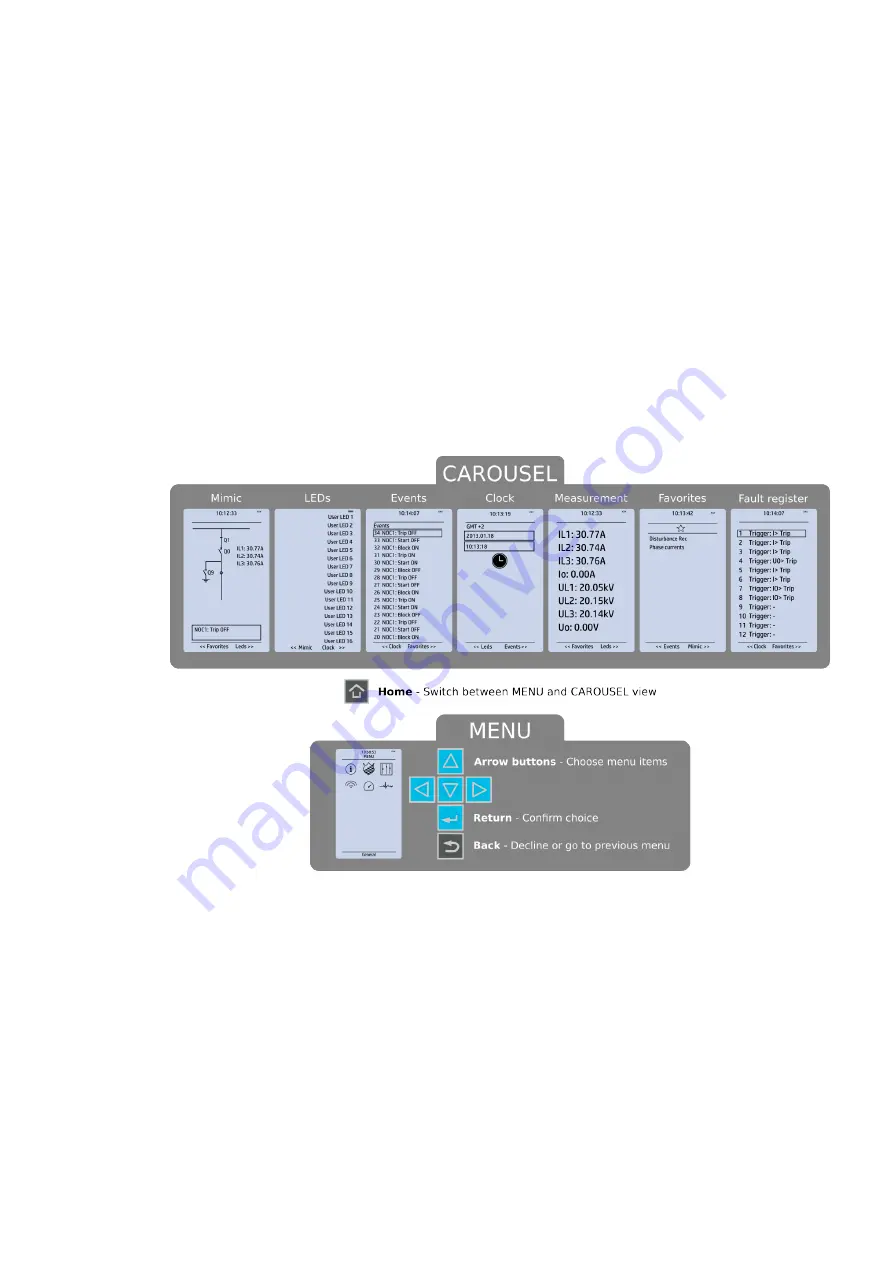
The user interface is divided into seven (7) quick displays: "Mimic", "LEDs", "Events", "Clock",
"Measurement", "Favorites" and "Fault register". The default quick display (as presented in the image
below) is the mimic view; you can move through these menus by pressing the left and right arrow
buttons. Please note that the available quick display carousel view might be different if you have
changed the view with AQtivate's Carousel Designer tool.
Figure. 4.2.1 - 2. Basic navigation (general).
The Home
Home button switches between the quick display carousel and the main display with the six (6)
main configuration menus (
General, Protection, Control, Communication, Measurements and
Monitoring). Note that the available menus vary depending on the device type. You can select one of
the menus by using the four navigation arrows and pressing EEnt
nter
er in the middle. The Back
Back button takes
you back one step. If you hold it down for three seconds, it takes you back to the main menu. You can
also use it to reset the alarm LEDs you have set. The password activation button (with the padlock icon
) takes you to the password menu where you can enter the passwords for the various user levels (User,
Operator, Configurator, and Super-user).
4.2.2 Navigation in the main configuration menus
All the settings in this device have been divided into the following six (6) main configuration menus:
• General
• Protection
A
AQ
Q-S215
-S215
Instruction manual
Version: 2.04
13
Содержание AQ-S215
Страница 1: ...AQ S215 Bay control IED Instruction manual...
Страница 249: ...Figure 7 4 151 Example block scheme A AQ Q S215 S215 Instruction manual Version 2 04 248...
Страница 269: ...Figure 8 13 172 Device installation A AQ Q S215 S215 Instruction manual Version 2 04 268...
Страница 270: ...Figure 8 13 173 Panel cutout dimensions and device spacing A AQ Q S215 S215 Instruction manual Version 2 04 269...
Страница 287: ...10 Ordering information A AQ Q S215 S215 Instruction manual Version 2 04 286...


