6
940 Powerig®
(HK496)
Maintenance
PREVENTIVE MAINTENANCE
An effective preventive maintenance program includes
scheduled inspections to detect and correct minor troubles.
Perform the following steps monthly during normal use:
· Ensure secure fir of hydraulic and electrical fittings.
· Inspect hoses for signs of damage. Replace hoses if
abrasion is deeper than the surface texture.
· Rotate hoses end-for-end to equalize wear and fatigue.
· Inspect during operation to detect any abnormal heating,
vibration or leakage.
· Inspect hydraulic fluid. If contamination (particles, water,
sludge, etc.) is detected, clean reservoir and replace fluid.
· Clean exterior surfaces.
· Check supply voltage. Do not operate the Powerig®
Hydraulic Unit if the line voltage is more than 5 percent
above or below 115 Volts.
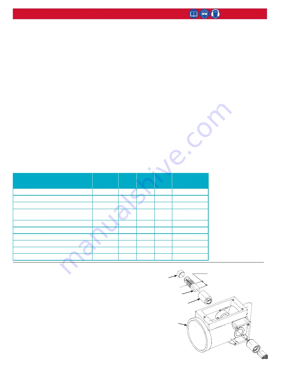
· Check motor brushes. See figure below.
SPARE PARTS
The quantity of spare parts that should be kept on hand
varies with the application and number of the Powerig
Hydraulic Units in service. Parts that should be available to
the service technician are: Pump-to-Motor Coupling, Relay,
Transformer, Pilot Valve, and Motor Brushes. See
Options
and Accessories
section of this manual for part numbers.
DIRECTIONAL VALVE OVERHAUL
If overhaul of the directional valve is necessary, a valve repair
kit that has the spools, cartridges & poppets is 129437,
is available for purchase, and should be kept on hand. To
rebuild valve, follow instructions included with kit.
PUMP OVERHAUL
If pump requires overhaul return it, or the complete unit, to
the nearest repair facility shown on the inside back cover.
REPLACING PUMP-TO-MOTOR COUPLING
Pump-to-motor coupling can be replaced by removing four
socket cap screws holding the motor housing to the cover
plate and lifting the motor to one side. Lift out the original
coupling with needle-nose pliers. Drop in the new coupling,
align the slots and reassemble motor to cover plate.
INTERNAL ADJUSTMENT OF PRESSURE SWITCH
1. Remove the top cover of the switch.
2. Loosen two screws located in bottom of switch housing.
3. Place a 0.20-inch-thick shim between the spring retainer
and the platen.
4. Loosen the set screw on the spring retainer until it
contacts shim.
5. Lock the spring retainer in place with the set screw.
6. Slide the switch mounting bracket toward the switch
button until it contacts the platen surface.
7. Secure with two screws located in the middle of the
bottom cover.
8. Connect a volt/ohm meter to the electrical cord.
9. Tighten the switch adjustment screw against the switch
mounting bracket until the switch button contacts the
platen and actuates. The volt/ohm meter will react when
the button actuates. A click can be heard.
10. Continue tightening the switch adjustment screw 1/8 of a
turn after the switch button actuates.
11. Replace the top cover of the switch.
CHECKING MOTOR BRUSHES
Checking motor brushes frequently helps to prevent premature failure
of the armature. To check the brushes:
1. Remove the metal brush cover plates.
2. Unscrew the plastic brush holder caps.
Note: Springs on the
brushes will push on the caps. Hold the caps as they are
loosened.
3. Remove brush assemblies.
4. Clean copper commutators on the armature with a pencil eraser.
5. Clean out spaces between connections with a plastic tool. If
commutator is damaged or worn, replace armature with Armature/
Field Kit, which is included in the Motor Service Kit. See
Options
and Accessories
section of this manual for part numbers.
6. Measure the length of the carbon brush, and replace both brushes
if either one is 1/4 inch or less in length.
7. Install brush assemblies, brush holder cups, and metal brush cover
plates.
(Spring)
Brush
Brush
Holder Cap
Brush
Holder
Replace both brushes
if either one is less than
1/4 inch in length.
Motor
Shell
SERVICE PERIOD
ACTION
BEFORE
EACH
USE
EVERY
50
HOURS
EVERY
100
HOURS
EVERY
200
HOURS
Hydraulic Hose Fittings
Check-Clean
•
Electrical Connections
Check
•
Hydraulic Fluid Level, Fill Cap Tight
Check
•
Verify Pull & Return Pressure, Tighten
Adjustment Screw Jam Nuts
Check
•
Tighten Cover Plate Screws
Check
•
Tighten Screws on Engine
Check
•
Change Hydraulic Fluid, Clean Tank
Change
• (Notes
1
and
2
)
Check Motor Brushes
Check
•
Directional Valve Seals, Poppets & Seats
Check
• (Note
3
)
External Relief Valve Stem
Check
• (Note
4
)
Notes:
1. Service more frequently
when used in dusty
areas.
2. Hydraulic fluid: use
32AW (0°F - 70°F
ambient), 46AW (30°F -
120°F ambient), or ATF
(30°F - 90°F ambient).
3. If poppets show wear,
use Huck Directional
Valve Kit to replace
poppets, seats & seals.
4. If valve stem shows
wear, replace with Huck
Valve Stem.


