


Do not store the radio system in extreme heat
or cold, in direct sunlight, in high humidity, in
high vibration environments or in dusty areas.
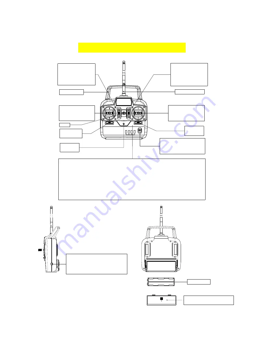
NAME AND HANDLING OF EACH PART
Servo reversing switches (Option Function)
Switches that reverse the direction of operation of the servos
The lower position is the normal side and the upper position is the reverse side.
Channel display Operating direction display
AIL. : Aileron(CH1) REV. : Reverse side
ELE. : Elevator(CH2) NOR. : Normal
THR. : throttle(CH3)
RUD. :Rudder(CH4)
Power switch
in the upper position,
the power is turned on
.
LED
Power on
Hook
Aileron
trim lever
Rudder trim
lever
Throttle (model 1)
Elevator (model 2)
/Aileron stick
Elevator (model 1)
Throttle (model 2)
/rudder stick
Carrying bar
2.4G Antenna
Throttle trim lever
(model 1)
Elevator trim lever
(model 2)
Elevator trim lever
(model 1)
Throttle trim lever
(model 2)
Battery Box Cover
Use when replacing the battery
Battery Box
Charging Jack
Charging jack when the transmitter
was converted to NiMh battery system.
Aileron Control (CH1):
When the aileron stick
is mover to the right, the right aileron is raised


