background image

Network Dome Camera·

Quick Start Guide


20 

20 


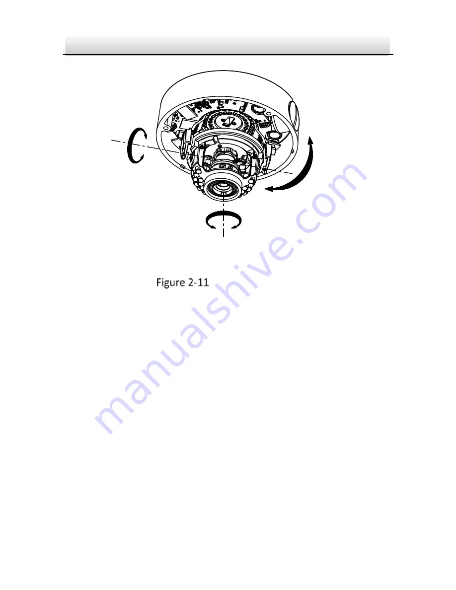
3-axis Adjustment 

2.


Zoom and focus adjustment. 

1).


View the camera image using the monitor. 

2).


Loosen the zoom lever and move the lever between T (Tele) 

and W (Wide) to obtain the appropriate angle of view. 

3).


Tighten the zoom lever. 

4).


Loosen the focus lever and move the lever between F (Far) and 

N (Near) to obtain the optimum focus. 

5).


Tighten the focus lever. 

Rotation

Panning

Tilting

Содержание XC-MD-22V-IR

Страница 1: ...1 Camera Network Dome Camera Quick Start Guide XC MD 22V IR quick guide ...

Страница 2: ...mprove or update the products or procedures described in the manual DISCLAIMER STATEMENT Underwriters Laboratories Inc UL has not tested the performance or reliability of the security or signaling aspects of this product UL has only tested for fire shock or casualty hazards as outlined in UL s Standard s for Safety UL60950 1 UL Certification does not cover the performance or reliability of the sec...

Страница 3: ...area is likely to cause harmful interference in which case the user will be required to correct the interference at his own expense FCC Conditions This device complies with part 15 of the FCC Rules Operation is subject to the following two conditions 1 This device may not cause harmful interference 2 This device must accept any interference received including interference that may cause undesired ...

Страница 4: ...recyclethis info 2006 66 EC battery directive This product contains a battery that cannot be disposed of as unsorted municipal waste in the European Union See the product documentation for specific battery information The battery is marked with this symbol which may include lettering to indicate cadmium Cd lead Pb or mercury Hg For proper recycling return the battery to your supplier or to a desig...

Страница 5: ...ns are neglected Warnings In the use of the product you must be in strict compliance with the electrical safety regulations of the nation and region Please refer to technical specifications for detailed information Input voltage should meet both the SELV Safety Extra Low Voltage and the Limited Power Source with 24 VAC or 12 VDC according to the IEC60950 1 standard Please refer to technical specif...

Страница 6: ...upply voltage is correct before using the camera Do not drop the camera or subject it to physical shock Do not touch sensor modules with fingers If cleaning is necessary use clean cloth with a bit of ethanol and wipe it gently If the camera will not be used for an extended period please replace the lens cap to protect the sensor from dirt Do not aim the camera at the sun or extra bright places Blo...

Страница 7: ...capacitor of the equipment shall be replaced regularly according to their average enduring time The average time varies because of differences between operating environment and using history so regular checking is recommended for all the users Please contact with your dealer for more details Improper use or replacement of the battery may result in hazard of explosion Replace with the same or equiv...

Страница 8: ...t Guide 7 Table of Contents 1 Appearance Description 8 2 Installation 10 Disassembling 11 Mounting 12 2 2 1 Ceiling Mounting 12 Image and Focus Adjusting 19 3 Setting the Network Camera over the LAN 22 4 Accessing via Web Browser 25 ...

Страница 9: ...Network Dome Camera Quick Start Guide 8 1 Appearance Description The overview of the network dome camera is shown below Overview 4 2 3 1 ...

Страница 10: ...iner 3 Lens 4 Mounting Base 5 Reset 6 Auxiliary Video Output 7 Serial Port 8 Micro SD Card Slot 9 Network Cable 10 Power Cable Press RESET about 10s when the camera is powering on or rebooting to restore the default settings including the user name password IP address and port No etc ...

Страница 11: ...uct does not function properly please contact your dealer or the nearest service center Do not disassemble the camera for repair or maintenance by yourself Make sure that the wall is strong enough to withstand three times the weight of the camera For the camera that supports IR you are required to pay attention to the following precautions to prevent IR reflection Dust or grease on the dome cover ...

Страница 12: ...st be seated flush against the inner surface of the bubble to isolate the lens from the IR LEDS Fasten the dome cover to camera body so that the foam ring and the dome cover are attached seamlessly Disassembling Steps 1 Loosen the three screws on the edge of the bubble with the screw driver 2 Open the bubble and remove the inner black liner as shown in Figure 2 1 Remove the Bubble and Black Liner ...

Страница 13: ...ou want to fix the camera 3 According to the drill template as shown in Figure 2 2 drill three screw holes in the ceiling The Drill Template 4 If you want to route the cables inside the ceiling drill a cable hole in the ceiling according to the drill template Skip this step if you Cable Outlet Screw Hole Drilling Template for Outdoor Day Night Vandal proof Dome Camera Side Cable Outlet ...

Страница 14: ...ure the camera with the supplied screws as shown in Figure 2 3 Secure the Camera 7 Route the cables through the cable hole 8 Connect the video output connector to the monitor Connect the power connector to the power supply 9 Adjust the image and focus Please refer to the section 2 3 for more detailed information 10 Install the inner black liner back to the camera 11 Install the bubble back to the ...

Страница 15: ...er and Bubble Conduit Installation on the Side If you want to route the cables from side of the camera you need to follow the steps below to install a conduit for cable routing Steps 1 Rotate the water proof plug counterclockwise to remove it from the camera ...

Страница 16: ...e the water proof plug 2 Route the power cable and network cable through the side outlet to the conduit 3 Align and rotate clockwise the conduit to the side outlet tightly Install the Conduit to the Camera Water proof Plug Side Cable Outlet Conduit ...

Страница 17: ...Network Dome Camera Quick Start Guide 16 For wall mounting position the side outlet directly downward for water proof Side Outlet Direction Downward ...

Страница 18: ...t 2 Align the camera with the mounting base 3 Tighten the set screws to secure the camera with the mounting base 4 Connect the video output connector to the monitor Connect the power connector to the power supply 5 Adjust the image and focus Please refer to the section 2 3 for more detailed information Mounting Adapter Mounting Base ...

Страница 19: ...Network Dome Camera Quick Start Guide 18 Secure Camera 6 Install the inner black liner back to the camera 7 Align the bubble with the camera 8 Tighten the screws to secure the bubble with the camera ...

Страница 20: ...s Adjusting Steps 1 3 axis adjustment 1 View the camera image using the monitor 2 Rotate the panning table to adjust the panning position of the camera 3 Rotate the tilting axes to adjust the tilting position of the camera 4 Rotate the lens table to adjust the azimuth angle of the image ...

Страница 21: ... image using the monitor 2 Loosen the zoom lever and move the lever between T Tele and W Wide to obtain the appropriate angle of view 3 Tighten the zoom lever 4 Loosen the focus lever and move the lever between F Far and N Near to obtain the optimum focus 5 Tighten the focus lever Rotation Panning Tilting ...

Страница 22: ...justment When installing the camera outside use the XC RC MD 01 rain cover to avoid rain on the dome bubble It might still happen that the bubble becomes blur the IR Led might reflect in the camera To avoid clean the bubble regularly Zoom Focus Lever ...

Страница 23: ...address of network camera The following figure shows the cable connection of network camera and PC Wiring over LAN Set the IP address of the camera for accessing via LAN Steps 1 Use Xyclop CCTV client software to detect the online devices Please refer to the user manual of Xyclop CCTV client software for detailed information Search online devices automatically After launch Xyclop CCTV software it ...

Страница 24: ...e Devices Device can be searched and displayed in the list in 15 seconds after it went online it will be removed from the list in 45 seconds after it went offline Search online devices manually You can also click Refresh Every 15s to refresh the online device list manually The newly searched devices will be added to the online list 2 Change the IP address and subnet mask to the same subnet as of y...

Страница 25: ... click OK to save the changes Modify Network Parameters The default IP address is 192 0 0 64 The default user name is admin and the password is 12345 It is highly recommended you change the initial password after your first login to avoid security problems For accessing the network camera from different subnets please set the gateway for the network camera after you log in ...

Страница 26: ... 1G or higher Display 1024 768 resolution or higher Web Browser Internet Explorer 6 0 and above version Apple Safari 5 02 and above version Mozilla Firefox 3 5 and above version and Google Chrome8 and above version Steps 1 Open the web browser 2 In the browser address bar input the IP address of the network camera e g 192 0 0 64 and press the Enter key to enter the login interface 3 Input the user...

Страница 27: ...e 1 Login Interface 5 Install the plug in before viewing the live video and managing the camera Please follow the installation prompts to install the plug in You may have to close the web browser to finish the installation of the plug in ...

Страница 28: ...Network Dome Camera Quick Start Guide 2 Download Plug in Install Plug in 1 ...

Страница 29: ... Start Guide 3 Install Plug in 2 6 Reopen the web browser after the installation of the plug in and repeat steps 2 4 to login For detailed instructions of further configuration please refer to the user manual of network camera ...

Отзывы: