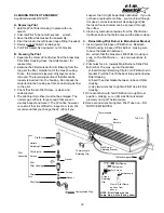
AquaStar 80 VP Скачать руководство пользователя страница 20

20

Thermostat
Tubing to
Heat Exchanger

Calibration Screw

Thermostat
Piston
Assembly

Spring

Correct height
of spring - 5/32"
or 4mm

Note: Unless setting #8 (145°

± 

5, this is scalding hot water)

is needed for some rare occa-
sion we highly recommend run-
ning the heater on setting 4 or
5. This will also avoid the need
to mix a lot of cold water.

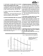
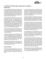
1. Turn AquaStar temperature setting to #8.  This is all the way to the right, clockwise.
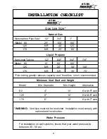
2. Turn on a hot water tap at the flow which will turn the AquaStar burners on.  If the heater is working

correctly, this minimum activation flow will be 3/4 of a gallon a minute, for Model 125/80 and 1.1 for
Model 170.  This is a flow that can fill up a quart jar in 20 sec. for the Model 125/80 and 15 sec. for the
Model 170.  If the necessary flow to activate burners needs to be higher than the required minimum, see
water valve trouble shooting in your manual.  The burners will come on at maximum fire and, within a
minute or so the burner flames will stabilize to a lower flame.  Water temperature should be around
145°± 5.  (This is scalding and too hot to put your hand under.)  You should not be able to hold on to the
hot water pipe on the left side of the AquaStar.

3. Next turn the temperature dial all the way to the left to the lowest setting #2.  Burner flames will become

quite small and should remain small.  Water temperature, after a minute or so, should stabilize at about
105°± 5.  Holding the hot water pipe should be comfortable.

4. Leaving temperature setting at #2, now, increase water flow on higher.  You should see the burner

flames increase in size, and then decrease when you reduce the water flow.

5. Note:  If all of the above performs according to this description, the thermostat is working correctly.

SYMPTOMS OF A DEFECTIVE OR IMPROPERLY CALIBRATED THERMOSTAT:

The hot water is too hot.  Usually this results in the heater shutting down on overheat
safety. The pilot frequently goes out and needs to be relighted.

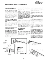
PROCEDURE TO CALIBRATE THERMOSTAT
(See diagram for correct location of screw to recalibrate)

1.Turn calibration screw in clockwise all the way, compressing the spring.
2.Back out screw 1 1/2 full turns. When set at the factory, the space from top to
    bottom portion of the spring should be approximately 5/32" or 4mm.

NOTE: Turning the screw in (up) reduces the burner flames. Unscrewing it increases the

flames. If a thermostat is in good condition, and the calibration screw is properly
adjusted, the water temperature should be 145° (± 5) when temperature dial setting is
set at #8 and water is flowing at the minimum burner activating flow of
3/4 of a gallon a minute (Model 125/80) or 1.1 gpm (Model 170).

NOTE:   Sometimes as a thermostat gets old (5 yrs or so), the space on the screw

adjustment may be too loose. In that case, turn the screw in another half or full turn more
if need be. It is important that you do not back this screw out so far that the burner
flames do not modulate and burners are always on full. Without modulation, the heater
will overheat and shut down.

TEST PROCEDURE TO CONFIRM THERMOSTAT IS WORKING PROPERLY

CALIBRATION AND THERMOSTAT TEST

Temperature Dial

Содержание 80 VP

Страница 1: ...s phone Follow the gas supplier s instructions If you cannot reach your gas supplier call the fire department Installation and service must be performed by a qualified installer service agency or the...

Страница 2: ...burners and is ignited by the pilot flame The heat exchanger then absorbs the heat generated by the burners and transfers it to the cold water as it travels through the heat exchanger When the hot wat...

Страница 3: ...GAS PRESSURE FOR HIGH ALTITUDES The pressure regulator provided with the heater is set to deliver the proper gas pressure as indicated on the rating plate and in the manual for altitude up to 2500 fe...

Страница 4: ...stic potable water a mixing valve or other similar device must be provided to reduce scald hazard potential DO NOT CONVERT AN EXISTING CLOSED HOT WATER HEATING SYSTEM TO A COMBINATION SPACE AND POTABL...

Страница 5: ...days 9 Should overheating occur and the gas supply fail to shut off turn off the manual gas control valve to the appliance 10 See instructions on setting the water tempera ture page 12 11 Do not use...

Страница 6: ...P M Z K H J G F D E C B A I Y Fig 2 Parts of AquaStar 80 L T pilot V overheat shut off sensor W draft hood X rating plate serial gas type etc Y incandescent particles tray Z gas pressure testing nippl...

Страница 7: ...t water lines insulated 6 Having a floor drain or sink nearby is handy in case you need to drain water from your heater 7 Place the heater in a location where water leaks will do NO DAMAGE to adjacent...

Страница 8: ...reful not to lose the washers Re move your heater from the Water and Gas Con necting Strip Now you can make your water and gas connections as explained in the following sections When all connections h...

Страница 9: ...lator to the gas piping the indicator arrow on the regulator must be pointed in the direction of gas flow NOTE The regulator supplied with the heater is an appliance level regulator de signed for low...

Страница 10: ...lowing all local ordinances and specifications for installing a gas appliance vent or chimney The gasses to the outdoors under all operating con venting system must be constructed so as to develop a p...

Страница 11: ...r Immediately call a qualified service technician to inspect the appliance and to replace any part of the control system and any gas control which has been under water LIGHTING INSTRUCTIONS 1 STOP Rea...

Страница 12: ...should be serviced periodically de pending on hardness of water and conditions of use or whenever signs of corrosion appear at the gas and water valve joint Servicing the water valve consists of repl...

Страница 13: ...column Yellow flames could be a sign of wrong size gas orifices or dirty burners If some burn ers have yellow flames while others have good flames it is likely that dust lint or spider webs have parti...

Страница 14: ...urnished with the heater is designed for low PILOT WILL NOT LIGHT 1 No gas to the AquaStar A Gas cock on gas line may not be open B AquaStar manual shut off valve at base of heater is not open Turn ha...

Страница 15: ...years old it is very unlikely that they are faulty Before testing reconfirm that 2 is absolutely cor rect and all connections are clean and tight To test the thermocouple disconnect the thermo couple...

Страница 16: ...e is good To test the electromagnet reconnect the thermo couple and take another reading The reading should drop to about 14 mv If it does not re place the electromagnet PILOT LIGHTS BUT GOES OUT DURI...

Страница 17: ...ature selector dial on 4 or 5 For more information see section on Setting Water Temperature Page 12 2 Inlet water temperature is too high as with preheated water Note Only the Model S AquaStar should...

Страница 18: ...t In such cases when mixing cold water at the tap the lower hot water pressure may be overpowered by a much higher cold water presure which may cause the AquaStar burners to shut down Make sure fau ce...

Страница 19: ...Housing b Insert the other Gasket between tube and Filter Housing c Use two wrenches to tighten Pilot Tube to Filter Housing 1 One wrench should hold Pilot Burner in right most position making sure ri...

Страница 20: ...4 Leaving temperature setting at 2 now increase water flow on higher You should see the burner flames increase in size and then decrease when you reduce the water flow 5 Note If all of the above perfo...

Страница 21: ...omponents O Ring and Steel Wedge prior to installing the replacement thermostat 1 Shut off gas to the heater by turning the handle on the main gas valve 2 Shut off the water supply to the heater and o...

Страница 22: ...s Flow Shut off Valve 14 provides a quick gas shut off right on the heater The gas shut off safety devices are integrated with the pilot light An Electro Magnet in the Gas Valve ensures thatgasflowsto...

Страница 23: ...LY 9 PILOTLIGHT 10 PILOTLIGHTORIFICE 11 PILOTLIGHTGASFILTER 12 THERMOCOUPLE 13 ELECTROMAGNET GAS FLOW SHUT OFF VALVE 14 MANUAL GAS FLOW SHUT OFF VALVE 15 PILOT STARTER KNOB 16 THERMOSTATIC MODULATOR A...

Страница 24: ...RIGHT SIDE PANEL 38799 LEFT SIDE PANEL 22527 TEMPERATURE SELECTOR KNOB 23617 PANELRETAINING SCREW 28329 PILOT STARTER KNOB 36540 FRONT PANEL 33993 INCANDESCENT PARTICLETRAY HOUSING COMPONENTS DIAGRAM...

Страница 25: ...LECTING STRIP 25776 WASHER 25779 HEAT EXCHANGER FRAME RETAINING SCREW 27126 WASHER 29596 THERMOCOUPLE ELECTROMAGNET LEAD WIRE TERMINAL RETAINING SCREW 29910 INLET WATER FLOW RESTRICTOR 31851 COLD HOT...

Страница 26: ...S 36546 BURNER MANIFOLD WITH LP INJECTORS 36548 LP GAS SLOW IGNITION MEMBRANE ASSEMBLY 36549 LP MAIN VALVE ASSEMBLY 36650 NG MAIN VALVE ASSEMBLY 37167 MODEL S GAS MAIN VALVE ASSEMBLY 37613 MODEL S NG...

Страница 27: ...opane Natural Gas Model 80 25 100 150 170 NR 25 80 Model 80 15 50 100 125 NR 20 50 100 170 NR NR 35 70 Flex tubing greatly reduces capacity and therefore is not recommended Minimum Vent Size and Heigh...

Страница 28: ...l use and service within the applicable periods specified below in accordance with the terms of this warranty The CEC replacement will be warranted for the unexpired portion of the original warranty T...

Отзывы: