Aqua Thermal X R Series Скачать руководство пользователя страница 8


User Manual Thermal X - R Series Chillers   


Page 8 

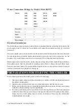
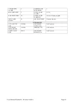
Water Connection Fittings by Model (Male BSPT) 

Models: 

R150 

R180 

R230 

R300 

R330 

R420 

R540 

R670 

R830 

R1000 

R1200 

R1330 

R1500 

R2000 

R2500 

R3000 

R4000 

Water Out: 

1” 

1” 

1½” 

2½” 

Water In: 

1” 

1” 

1½” 

2½” 

Drain: 

1” 

1” 

1” 

1” 

Overflow: 

1” 

1” 

1” 

1” 

Water Supply: 

½” 

½” 

½” 

½” 

Electrical Installation 

The chiller draws a large amount of current and it is important that the connection of the unit to the 

power supply must be carried out  in  accordance with  Australian standards  and only  by a licensed 

electrician. 

The power supply system on-site and the circuit protection must be designed for the total current of 

the unit taking into account the inrush current and the lock rotor amps of the compressor– see the 

brochure. The circuit breaker must be set no more than 125% of the units rated load current.  

Mains supply cables must be sized to ensure adequate voltage at the chiller under all load conditions. 

Three-phase  power  must  be  symmetrical,  ensuring  equal  effective  voltage  and  equal  phase  angle 

between consecutive phases. The pump and the compressor rely on correct phase rotation. Ensure all 

electrical connections are tight prior to starting up.  

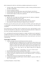
PREPARATIONS FOR STARTING THE CHILLER 

For the initial operation of the chiller, please confirm the following: 

1.


The power supply voltage and phase should be in accordance with the specifications listed on 
the chiller’s marking plate. 

2.


Check the pipe and return water pipe are connected properly and the valve is open.  

3.


Fill the water tank with water or coolant before starting the water pump. (Ensure you are using 
a suitable coolant according to your requirements) 

4.


For water-cooled units, please pay attention to the moving direction of the water pump and 
confirm the tower fans are not moving in the opposite direction. If the pump is three-phase, 
change  any  two  relative  phase  lines  to  reverse  its  direction.  Then  close  the  switch  after 
connections have been made. 


Содержание Thermal X R Series

Страница 1: ...s Page 1 Revision 2 AUGUST 2019 Thermal X R Series Owner s Manual This guide applies to the following models R150 to R4000 Aqua Cooler Pty Ltd U14 2 12 Knobel Court Shailer Park 4128 Qld www aquacoole...

Страница 2: ...ng Sequence 9 Operating Precautions 9 CHLF2 60 10 CHLF4 60 10 CHLF12 40 11 CDMF20 4 11 CDMF32 30 12 Aqua Cooler Controller 12 Unlocking the Keypad on the Aqua Cooler Controller 12 Operational Logic of...

Страница 3: ...chematic 24 Poor Heat Dissipation 26 Low Refrigerant 26 Low and High Pressure Difference 27 Compressor Not Starting 27 Maintenance 27 Recommended Preventative Maintenance Program 28 Warranty 28 Genera...

Страница 4: ...process cool They are supplied with an immersed coiled evaporator or plate heat exchanger or shell tube evaporator model dependant an air cooled condenser and a rotary or scroll compressor to circula...

Страница 5: ...ould be secured to prevent it from toppling over Minimum temperature setting is 5 C on the unit Any lower than this may cause problems with the evaporator icing up and potentially loss of refrigerant...

Страница 6: ...possible If the unit is to be stored before installation then care must be taken to ensure no foreign matter can get into the water pipes If the storage is for a prolonged period it is recommended tha...

Страница 7: ...ort the chiller s full operating weight Installation of the Water Path Before connecting the make up water check the suction pressure on in the chiller to ensure there is no refrigerant leak A refrige...

Страница 8: ...ltage at the chiller under all load conditions Three phase power must be symmetrical ensuring equal effective voltage and equal phase angle between consecutive phases The pump and the compressor rely...

Страница 9: ...oints and operational parameters are displayed on the screen Any faults are indicated on the face of the control panel It is a good idea after the unit has been running for 5 minutes check that the wa...

Страница 10: ...R230 R300 R330 CHLF2 60 R420 R540 R670 R830 R1000 R1200 R1330 CHLF4 60 R1500 R2000 R2500 CHLF12 40 R3000 CDMF20 4 R4000 CDMF32 30 CHLF2 60 Model Driving Motor Q 3 0 5 1 0 1 5 2 0 2 5 3 0 3 5 CHLF2 60...

Страница 11: ...12 40 Model Driving Motor Q 3 7 8 9 10 11 12 13 14 15 16 CHLF12 40 2 4 3 3 H 47 46 45 43 5 41 5 39 5 37 5 35 31 5 27 5 CDMF20 4 Model Driving Motor Q 3 0 10 12 14 16 18 20 22 24 26 28 29 CHLF12 40 5 5...

Страница 12: ...7 AQUA COOLER CONTROLLER The chiller unit features an interface panel with LCD display and input buttons to configure certain functions of the unit Unlocking the Keypad on the Aqua Cooler Controller T...

Страница 13: ...eratures too high or too low Temperature Control High and Low Temperature Alarm Stop High and low temperature limits can be set in order that if they are breached then the chiller will shut down In ra...

Страница 14: ...et to run if the chiller develops a fault by turning this feature ON in the program will keep water to the process This water will of course get warm but it is designed to keep the process cool long e...

Страница 15: ...the set point is 10 C the hystersis 2 C and the close tolerance 1 C then the controller will attempt to keep the temperature between 10 5 C and 11 5 C The ability of the chiller to keep the temperatur...

Страница 16: ...ER TEMP will show Press the escape key to revert to home page Temperature Hysteresis Temperature between refrigeration circuits cut out and cut in Scroll to the PARAMETERS MENU then to the SET POINTS...

Страница 17: ...by pressing the OK button Range Low 5 C to 10 C High 10 C to 40 C Scroll to PARAMETER MENU and to the SET POINTS sub menu Scroll to HIGH TEMP ALARM and LOW TEMP ALARM and press OK SET HI TEMP ALARM wi...

Страница 18: ...nded that the setting is not greater than 1 or 2 minutes Tandem Installation Assigning the chillers into a single or tandem set installation Scroll to PARAMETER MENU and then to the SYSTEM sub menu Sc...

Страница 19: ...allation YES on master chiller in N 1 installation VAR SPEED FUNCTION OFF On for chillers fitting with VFD on compressor or the pump NO HE SENSORS 0 LOW TEMP STOP YES AUX INPUTS N O FAN SPEED CONTROL...

Страница 20: ...RM 1 0 1 L s MAX TEMP LIMIT 20 SUPPLY FLOW WARNING 1 Varies with pump supplied SET PT AMB OTEMP 45 SET POINT TEMP Customer Specific SENSOR MENU CCT1 SUCT PR SIZE 0 10 Bar SECONDARY SUPPLY CAL See Proc...

Страница 21: ...vice Number 2012 ModBus RTU Slave Addr 1 247 head in the Chiller ID tab Again use the save password aquacustomer as the password 7 Then edit the page to the new IP address details for the chiller agai...

Страница 22: ...e approximately 3 weeks of data logging 10 second intervals will only give 24 hours of data logging and the logging drops the old files off the end so if the unit has a problem and it takes more than...

Страница 23: ...ted to the internet or to a BMS system the BIN file will need to be updated as well to the corresponding issue number Using a laptop connect to the Aqua Cooler controller via the Ethernet card in the...

Страница 24: ...oss the bottom of the board IN1 NOT USED IN1 IN2 IN3 IN4 IN5 IN6 IN7 IN8 IN9 IN10 Not Used 0 10V Input 0 10V NC Input 0 10V NC Input 0 10V NTC thermistor 0 10V NTC thermistor 0 10V NTC thermistor 0 10...

Страница 25: ...no other equipment in the vicinity that may be throwing heat onto the unit or that the unit has not been installed improperly Faulty HP transducer or HP switch replace Low pressure LP alarm tripping F...

Страница 26: ...ck operation of transducer reading correctly Low refrigerant charge Check refrigerant system operation check super heat and sub cooling are with in normal operating ranges High Ambient Temp Faulty pro...

Страница 27: ...pressure switch is damaged 5 The overload protector of the compressor is damaged 6 The electromagnetic relay is damaged or the overload protector is damaged 7 The water level is too low 8 The refrige...

Страница 28: ...be excluded under Australian Consumer Law You are entitled to replacement or refund for a major failure and to compensation for other reasonably foreseeable loss or damage You are also entitled to ha...

Страница 29: ...User Manual Thermal X R Series Chillers Page 29 Installation Sketch Map of Air Cooled Chiller...

Страница 30: ...User Manual Thermal X R Series Chillers Page 30 Installation Sketch Map of Water Cooled Chiller...

Страница 31: ...User Manual Thermal X R Series Chillers Page 31 Internal Structure Sketch Map of Air Cooled Chiller...

Страница 32: ...User Manual Thermal X R Series Chillers Page 32 Internal Structure Sketch Map of Water Cooled Chiller...

Страница 33: ...of the completed table and send it back to us Customer and On Site Requirement Required Capacity kW Rated Ambient Temp C Rated Supply Temp C Rated Flow Rate L s Customer Address Machine Information C...

Страница 34: ...NO Ambient Temp C Water Set Point C Temp Controller Reading Check Fault Buzzer Light Works Sight Glass Clear Unit Handles Heat Load On Off Button Works Check Oil level on the compressor sight glass Op...

Страница 35: ...es and screws Commissioning by Inspected by Company Contact number Installation site Business name of site Site contact name Site contact phone no Sit contact position Note regarding to refrigeration...

Страница 36: ...User Manual Thermal X R Series Chillers Page 36 Agent signature Date Customer representative print name Customer representative signature Filing Aqua Cooler Date Print name Signature NOTES...

Отзывы: