13
Deutsch
English
Français
6 Elektrische
Anschlüsse
6.1 Klemmenanordnung
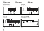
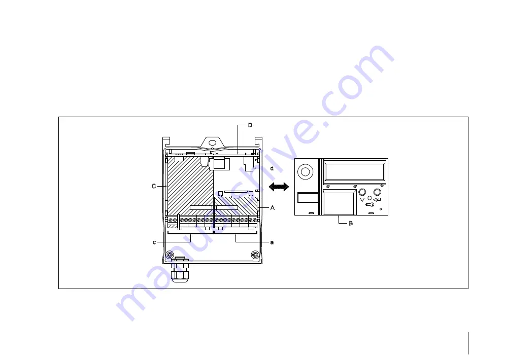
Die Grafik zeigt die möglichen Module und die An-
ordnung der Klemmen:
A: Klemmen-Modul
Klemmenblock a
B: Steckbares
Rechenmodul
C: Options-Modul
#1
Klemmenblock c
D: Options-Modul
#2
Klemmenblock d
6 Electrical
connections
6.1 Terminal assignments
The diagram shows an example of typical modules
and their terminal assignments:
A: Terminal module
terminal block a
B: Plug-in totaliser module
C: Optional module #1
terminal block c
D: Optional module #2
terminal block d
6 Connexions électriques
6.2 Disposition des bornes
Le graphique représente les modules possibles et la
disposition des bornes :
A: Module de bornes
bornier a
B: Module du calculateur enfichable
C: Module optionnel n° 1
bornier c
D: Module optionnel n° 2
bornier d
Содержание CALEC ST
Страница 10: ...10 7 Gehäuse schliessen Close casing Fermer boîtier 1 2 3 3 2 ...
Страница 24: ...24 ...
Страница 44: ...44 ...
Страница 55: ...55 Deutsch English Français 27 Bohrschablone 27 Hole template 27 Gabarit de perçage ...

