background image

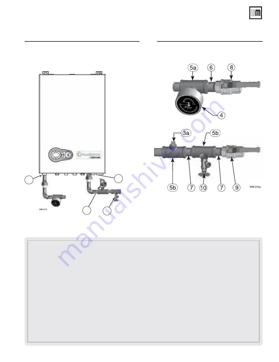
Figure 7


)NSTALLPIPINGCOMPONENTSREQUIREDFOR
HYDROSTATICTEST

see legend below) 

Part number 550-100-305/0916

 11 

AquaBalance

TM


W

ALL

 M

OUNT


GAS

-

FIRED


WATER


BOILER

 — C

OMBI


Boiler Manual

1.  Boiler Supply (outlet) connection, (male, 

 1”NPT ).

2.  Boiler Return (inlet) connection, (male, 

 1”NPT).

       Recommend Near Boiler Piping to be 1-1/4” NPT or larger.  Bushing 1” x 1-1/4” NPT at Supply (outlet) and Return (inlet) not 

shown. 

(

field supplied 

by installer

)

3.  Boiler relief valve, shipped loose with boiler — 

$/./4MOUNTRELIEFVALVEUNTIL!&4%2HYDROSTATICTESTING

.

3a. 

4%-0/2!2),9/.,9ˆ

 Insert a ¾” NPT plug in the relief valve tapping of the reducing tee. 

4HIS-534"%2%-/6%$

after the test and the relief valve mounted here

.

4. Pressure/temperature 

gauge, 

(

field supplied) 

by installer, (Optional – can use boiler gauge).

5a.  Reducing tee, NPT,  1

-1/4

 ” x 1

-1/4

” x ¼” 

(

field supplied) 

by installer .  

5b.  Tee, NPT,    1

-1/4

 ” x 1

-1/4

” x ¾” 

(

field supplied) 

by installer. 

6.  Nipple,  NPT,  1

-1/4

 ” x close 

(

field supplied) 

by installer.

7.  Nipple,  NPT, 1

-1/4

 ” x close  

(

field supplied) 

by installer.

8.  Isolation valve on supply connection, 

(

field supplied) 

by installer (

1-1/4”NPT).

9.  Isolation valve on return connection, 

(

field supplied) 

by installer (

1-1/4”NPT).

10.  ¾” NPT boiler drain valve, 

(

field supplied) 

by installer — after hydrostatic testing, move drain valve to lowest point on the return piping 

if not already there.

3  Prepare boiler 

continued

Figure 6


)NSTALLPIPElTTINGSFORRELIEFVALVEANDPRESSURE
TEMPERATUREGAUGEˆ

$/./4MOUNTRELIEF

VALVEUNTIL!&4%2HYDROSTATICTESTING

(see 

legend below)

"OILER2ETURN

INLET 

"OILER3UPPLY

OUTLET

2

3

1

10

Содержание WMB-155C

Страница 1: ...ply could result in severe personal injury death or substantial property damage When calling or writing about the boiler Please have boiler model number from the boiler rating label Quick Start Guide Pages 3 4 AquaBalance WMB 155C Wall Mount Gas Fired Combination Boiler Heating and Domestic Hot Water Installation Startup Maintenance Parts ...

Страница 2: ...gs 3 2 Prepare boiler location 6 3 Prepare boiler 8 4 Converting boiler to propane 12 5 Gas piping sizing gas lines 16 6 Venting air piping general 17 7 Commonwealth of Massachusetts installations 20 8 Vent termination requirements 21 9 Boiler room air openings 22 10 DIRECT VENT Sidewall with separate pipes 23 11 DIRECT VENT Sidewall concentric 25 12 DIRECT VENT Vertical with separate pipes 27 13 ...

Страница 3: ...NHIBITOR HAS BEEN ADDED AND THE WATER HAS BEEN CHECKED WITH THE SUPPLIED TEST KIT s ONDENSATE TRAP HAS BEEN lLLED WITH WATER s LECTRICAL CONNECTION FOR THE BOILER IS GROUNDED AND HAS CORRECT POLARITY s 6ENTING AND NTAKE IR 0IPING IS ALL SECURE SEALED AND INSTALLED AS INSTRUCTED IN THE BOILER MANUAL System start 1 Push ECO Comfort Power button to start boiler 2 03 shows on the display control softw...

Страница 4: ...Liquefied Petroleum Propane Gas Propane conversion kit optional sold separately see Figure 123 page 92 Equipment that maybe required for installation Digital or U tube manometer for checking gas line pressure Volt ohmmeter may be required for troubleshooting Combustion Analyzer to verify and adjust combustion 1 Quick Start Guide using default settings This unit must only be used for its intended pu...

Страница 5: ...ld weather boiler system components failures power out ages or other electrical system failures could result in frozen plumbing and water damage in a matter of hours For your protection take preventative actions such as having a security system installed that operates during power outages senses low temperature and initiates an effective ac tion Consult with your boiler contractor or a home securi...

Страница 6: ... that the installation complies with all applicable codes s Prevent boiler water and condensate from freezing Provide air openings to room Boiler alone in boiler room 1 No air ventilation openings into boiler room are needed if clearances around boiler are at least equal to the SERVICE clearances shown in Figure 2 page 7 2 For spaces that DO NOT supply the minimum service clear ances provide two o...

Страница 7: ...hese air openings must have free area of at least 1 square inch per 1 000 MBH of boiler input B Left side clearance to combustibles 1 0 inches minimum C Top of boiler clearance to combustibles 12 0 inches minimum D Right side clearance to combustibles 1 0 inches minimum E Bottom of boiler clearance to combustibles 12 inches minimum must be 18 inches above floor for garage installations F Clearance ...

Страница 8: ... Corrosive contaminants and likely locations 9OU MUST PIPE COMBUSTION AIR TO THE BOILER air intake Install air inlet piping for the boiler as described in this manual The air termination fitting must be installed with the clearances and geometry relative to the vent outlet depicted in this manual to ensure that flue products do not enter the air intake Ensure that the combustion air will not contain...

Страница 9: ...ters Forotherstudspacing providesecure solidmounting surface on which to attach the boiler wall mounting bracket 2 Wood stud wall Install bracket with lag screws 3 8 x 3 included in kit only into the studs 3 Metal stud wall Secure bracket and spacer board to studs with 3 16 inch toggle bolts and 3 16 inch flat washers not included with kit 4 Concrete or block wall Secure wall bracket with approved ...

Страница 10: ...drostatic test this plug must be removed and the relief valve must be installed Fill and pressure test 1 See Figure 6 page 11 for use with the following instructions 2 CLOSE the boiler drain valve item 10 Connect a hose to fresh water supply and to the drain valve 3 Place a bucket under the ends of the isolation valves item 8 and 9 to catch water drippings 4 CLOSE isolation valve item 9 then crack...

Страница 11: ...mounted here 4 Pressure temperature gauge field supplied by installer Optional can use boiler gauge 5a Reducing tee NPT 1 1 4 x 1 1 4 x field supplied by installer 5b Tee NPT 1 1 4 x 1 1 4 x field supplied by installer 6 Nipple NPT 1 1 4 x close field supplied by installer 7 Nipple NPT 1 1 4 x close field supplied by installer 8 Isolation valve on supply connection field supplied by installer 1 1 4 NPT ...

Страница 12: ...ationintheseinstructions is not followed exactly a fire an explosion or productionof carbonmonoxidemayresultcausing property damage personal injury or loss of life The qualified service agency is responsible for the proper installation of this kit The installation is not proper and complete until the operation of the converted appliance is checked as specified in the manufacturer sinstructionssuppli...

Страница 13: ...gas valve and contact gas supplier to correct the problem before attempting to start or operate the boiler Installing venturi F BOILER IS ALREADY INSTALLED You must turn off electrical supply to the boiler and close the external manual gas shut off valve to isolate the boiler during conversion Allow the boiler to cool if it has been operating Following conversion of an installed boiler follow all ...

Страница 14: ...pipe 4 Washer 5 Hex head screws 6 Gas valve venturi 7 O Ring 8 Blower 4 Remove three 3 Hex head screws holding the venturi Item 5 in place remove venturi replace with new propane venturi from kit Verify the venturi label information matches the boiler size WMB 155C Propane venturi has black label ensure Item 7 venturi O ring is in place see Figure 15 re insert three 3 Hex head screws to hold new v...

Страница 15: ...oiler see Figure 103 page 82 j Press the DHW buttons details 1 and 2 Figure 64 page 50 for 10 seconds k The boiler will return to standby mode 9 Turn on gas by opening gas valve check for leaks and continue boiler start up and adjustments staring on page 63 4 44 04 4 352 6 6 54 4 02 3352 The valve could be damaged by manometer fluid contamination Failure to comply could result in severe personal i...

Страница 16: ...ow the instructions beginning on page 12 to operate the boiler on propane Failure to comply could result in severe personal injury death or substantial property damage 0IPE SIZING FOR PROPANE GAS 1 Contact gas supplier to size pipes tanks and 100 lockup gas pressure regulator 0ROPANE SUPPLY PRESSURE 1 Adjust propane supply regulator provided by gas supplier for 13 w c maximum pressure 2 Pressure r...

Страница 17: ...er the appliances remaining on an existing vent system will operate satisfactorily 1 Seal any unused openings in the common venting system 2 Visually inspect the venting system for proper size and hori zontal pitch and determine there is no blockage or restriction leakage corrosion or other deficiencies which could cause an unsafe condition 3 Test vent system Insofar as is practical close all build...

Страница 18: ...ent air pipe length increases see rating data on Figure 131 page 99 for derate amounts SIDEWALL termination VERTICAL termination Separate pipes Note 1 PVC or PP Concentric Note 1 Separate pipes Note 1 PVC or PP Concentric Note 1 See page 23 See page 25 See page 27 See page 29 Size inches Materials Fig 21 page 19 Size inches Materials Fig 21 page 19 Size inches Materials Fig 21 page 19 Size inches ...

Страница 19: ... Obtain all materials from M G Simpson Duravent ENTROTHERM CO 3YSTEMS NNO LUE 3INGLE wall Obtain all materials from Centrotherm See manufacturer s literature for detailed information MUST USE LOCKING COLLAR ON EVERY JOINT STAINLESS STEEL PIPING MATERIALS Vent pipe AL29 4C stainless steel Heat Fab Inc Saf T Vent Z Flex Inc Z Vent II Dura Vent FasNSeal Metal Fab Inc CORR GUARD Certified for direct ve...

Страница 20: ...ueled heating appliance or equipment The sign shall read in print size no less than one half 1 2 inch in size GAS VENT DIRECTLY BE LOW KEEP CLEAR OF ALL OBSTRUCTIONS 4 30 4 The state or local gas inspector of the side wall horizontally vented gas fueled equipment shall not approve the installation unless upon inspection the inspector observes carbon monoxide detectors and signage installed in acco...

Страница 21: ...IONS 4HE MINIMUM DISTANCE FROM ADJACENT PUBLIC WALKWAYS ADJACENT BUILDINGS OPENABLE WINDOWS AND BUILDING IN THE ATIONAL UEL AS ODE 3 0 AND OR THE ATURAL AS AND 0ROPANE NSTALLATION ODE 3 Part number 550 100 305 0916 21 AquaBalanceTM WALL MOUNT GAS FIRED WATER BOILER COMBI Boiler Manual 8 Vent termination requirements ...

Страница 22: ...l other appliances in the room Unless specified otherwise by appliance manufacturer 47 openings each at least 1 square inch per Btuh of all other appliances in the room OR opening each at least 1 square inch per Btuh of all other appliances in the room Unless specified otherwise by appliance manufacturer 47 openings each at least 1 square inch per Btuh of all other appliances in the room OR opening ...

Страница 23: ...lations 3 The air inlet of a boiler is part of a direct vent connection It is not classified as a forced air intake with regard to spacing from adjacent boiler vents 0REPARE WALL PENETRATIONS 1 Air pipe penetration a Cut a hole for the air pipe Size the air pipe hole as close as desired to the air pipe outside diameter 2 Vent pipe penetration 3TEP Read and follow all instructions in this manual 4 P...

Страница 24: ...ir ter mination elbow by inser ting bird screens See Figure 25 page 23 Bird screens must be purchased separately See the parts list at the end of this manual for part numbers 2 Secure the elbows so they will butt against the sidewall ter mination plate 3 When completed the air termination coupling must be oriented at least 12 inches below the vent termination and at least 12 inches above grade or ...

Страница 25: ...ch con centric termination as described in this manual All vent pipes and air inlets must terminate at the same height to avoid possibility of severe personal injury death or substantial property damage 2 Place wall penetrations to obtain minimum clearance as shown in Figure 29 page 26 for U S installations 3 The air inlet of a boiler is part of a direct vent con nection It is not classified as a f...

Страница 26: ...wn in Figure 30 4 Before beginning vent and air piping from the boiler to the con centric termination mount and secure the concentric termination as shown in Figure 30 The vent and air piping must be securely supported and must not rest its weight on the boiler fittings Failure to properly support the vent and air piping could result in vent piping damage resulting in possible severe personal injur...

Страница 27: ...53 37 0 73 2 6 4 2 0 0 DO NOT use short radius elbows for vent or air piping Boiler performance could be affected Part number 550 100 305 0916 27 AquaBalanceTM WALL MOUNT GAS FIRED WATER BOILER COMBI Boiler Manual Allowable vent air pipe materials lengths Use only the vent materials and kits listed in Figure 22 page 19 Provide pipe adapt ers if specified 1 Locate the terminations such that the tota...

Страница 28: ...anufacturer s instructions Termination and fittings 1 Prepare the vent termination elbow and the air termina tion elbow Figure 31 page 27 by inserting bird screens Bird screens must be purchased separately See the parts list at the end of this manual for part numbers 2 The air piping must terminate in a down turned 180 de gree return bend as shown in Figure 31 page 27 Locate the air inlet pipe no f...

Страница 29: ...assemblies as described in this manual All vent outlets must terminate at the same height to avoid possibility of severe personal injury death or substantial property damage 2 Place roof penetrations to obtain minimum clear ance of 12 inches between the edges of adjacent vent pipes of other boilers for U S installations see Fig ure 34 page 30 3 The air inlet of a boiler is part of a direct vent co...

Страница 30: ...nd must not rest its weight on the boiler fittings DO NOT drill or screw into either the vent pipe or air pipe Failure to properly support the vent and air piping could result in vent pip ing damage resulting in possible severe personal injury death or substantial property damage When inserting the partially assembled termi nation kit through the roof penetration wrap plastic or other protection ov...

Страница 31: ...nd all supports have been installed Follow instructions to cover the end of the assembly with plastic before inserting through the roof penetration to prevent debris from blocking the air passages If necessary you can shorten the lengths of the inner and outer pipes for a shorter finished assembly But you must ensure the pipes butt correctly at both ends Failure to properly as semble the concentric...

Страница 32: ...the lengths given in the previous pages for either the air or vent piping 2 See Figure 37 for locations for attaching vent and air inlet adapters on to the boiler Air inlet adapter connection is made on right side of centered flue adapter 3 Remove vent exhaust protective paper prior to mounting vent adapter 4 Vent and air inlet adapters needed to be attached to top securely with four 4 10 32 large ...

Страница 33: ...t pipes Chamfer boiler end of vent pipe for ease of insertion The vent pipe end must be smooth and chamfered to prevent possible damage to sealing gasket in vent pipe adapter 2 Inspect vent or air adapter above verify no obstructions or foreign objects inside 3 Loosen clamp screw if used 4 Measure 2 inches from end of pipe and make a mark with felt tip pen 5 Applysmallamountof silicongreasetoendof...

Страница 34: ...heated to a temperature suitable for clothes washing dish washing and other sanitizing needs will scald and cause injury s Children elderly infirm or physically handi capped persons are more likely to be injured by hot water Never leave them unattended in or near a bathtub shower or sink Never allow small chil dren to use a hot water faucet or draw their own bath If anyone using hot water in the b...

Страница 35: ...cuit 2 See instructions beginning on page 46 for wiring information 3 If using a manual reset limit control or wiring in the manual reset circuit set boiler control limit at least 20 F less than the external manual reset limit i e set control no higher than 180 F for a 200 F external limit for example ACKmOW PREVENTER Use backflow preventer in the cold water supply piping if required by local codes...

Страница 36: ...nded that you locate the air separator and expan sion tank as shown in the suggested piping drawings on pages 36 37 Ensure that the expansion tank size will handle boiler and system water volume and temperature See tank manufacturer s instructions and ratings for details Additional tanks may be added to the system if needed to handle the expansion These tanks may be installed by connecting to tees...

Страница 37: ... the tank avoids air bubbling through the tank water and provides the proper fill height in the tank Figure 47 0IPING TO DIAPHRAGM OR BLADDER EXPANSION TANK Correctallleaks in the system or tank piping Leaks allow air to escape from the system and will cause water logging of the tank This will result in water loss through the boiler relief valve due to over pressurization NEVER use an automatic air...

Страница 38: ...from the top of the boiler Discharge line must be as short as possible and be the same size as the valve discharge connection throughout its entire length Discharge line must pitch downward from the valve and terminate at least 6 above the floor drain where any discharge will be clearly visible The discharge line shall terminate plain not threaded with a material serviceable for temperatures of 375...

Страница 39: ...D WATER BOILER COMBI Boiler Manual Zone Valve zoning primary secondary See Figure 49 1 This configuration is for zone valve systems using a boiler loop connected as a secondary circuit off of a primarysystemloop Systemswhoseflowcharacteristics do not comply with those listed in Figure 47 page 37 must pipe the boiler loop as a secondary circuit as show 2 Systems zoned with zone valves recommend use a...

Страница 40: ...stic water heating only or both Refer to field wir ing beginning on page 47 for instructions on wiring to circulators 2 The boiler and circulators can also be operated by a zone controller FOR Figure 50 and Figure 51 OTE 4HIS IS A COMMON LEGEND FOR ALL PIPING DIAGRAMS NOT ALL ITEMS LISTED APPEAR IN EVERY lGURE 1 WMB 155C wall mount boiler 2 Relief valve supplied by Installer field piped MUST be pipe...

Страница 41: ...losed type tank if connecting to a boiler that is equipped with an automatic vent System setup and settings 1 Hi temp emitters may be baseboards radiators fan coils or heat exchangers For cast iron radiation and old black iron pip ing systems a Dirt separator with a magnet must be installed on the return piping to protect the boiler heat exchanger 2 Add a mixing device Figure 51 item 24 to help en...

Страница 42: ...oilers for access and ser vicing If recommended dimensions are not possible provide at least the minimum clearances given on page 5 Also follow local codes 3 Provide a minimum 36 inch walkway in front of the boilers to ensure accessibility 4 Unpack assemble and mount boilers according to instructions in this manual 5 Provide clearance for installation of venting air piping gas pip ing expansion ta...

Страница 43: ...t comply withASTM D1785 F441 or D2665 Cement and primer must comply with ASTM D2564 or F493 2 Select a condensate pump if used that is approved for use with condensing boilers and furnaces The pump should have an overflow switch to prevent property dam age from condensate spillage The pump should have a minimum capacity of 4 GPH for the boiler 3 When sizing condensate pumps make sure to include the...

Страница 44: ...piping 6 Before placing boiler in operation check boiler and its gas connection for leaks a During any pressure testing at less than 13 w c close the gas shutoff valve and disconnect system gas piping At higher test pressures disconnect boiler and gas valve from gas supply piping Do not check for gas leaks with an open flame use bubble test Failure to use bubble test or check for gas leaks can caus...

Страница 45: ... Ensure that this inlet pressure can be obtained with all other gas appliances in the property working For natural gas or liquefied petroleum propane gas the pres sure required at gas valve inlet pressure port verify minimum gas pressure when all gas appliances are in operation a Maximum 13 w c with no flow lockup or with boiler on b Minimum 3 5 w c gas pressure with gas flowing verify during boiler ...

Страница 46: ...ded as required by National Electrical Code ANSI NFPA 70 latest edition All field wiring is made through the bottom of the boiler through two 2 black grommets shown in Figure 58 Connecting terminals The electrical connections terminal block can be accessed after removing the front jacket panel The layout of the terminals for the various connections is shown in Figure 59 or given in the wiring diagr...

Страница 47: ...tion block see Figure 59 Item 138 right side of block terminals 5 and 6 s 2ECOMMENDED WIRE SIZE 7 CONDUCTOR SHIELDED THERMO stat wire 22 gauge s OUNT ON NORTH EXTERIOR WALL shielded from direct sunlight or flow of heat or cooling from other sources approximately 10 feet above ground level s O 4 RUN SENSOR WIRES WITH OTHER ELECTRICAL WIRES Figure 61 UTDOOR SENSOR 21 Field wiring continued ...

Страница 48: ...l on Combi 186 Return temperature sensor 191 Exhaust temperature sensor 278 Double sensor heating safety 279 Transformer 115 24 Vac 284 Relay SPST Coil 24 Vac 370 LWCO optional 373 OPENTHERM communication Not used NOTES 1 All wiring must be installed in accordance with N E C and any other national state or local requirements 2 Room thermostat should be a dry contact type and should draw power from...

Страница 49: ...sensor 44 Gas valve 72 Room thermostat optional 81 Ignition electrode 95 Mixing diverting valve 104 1 Fuse 3 15A 104 2 Fuse 630mA 114 Water pressure switch 136 Flow meter 138 Outside temperature sensor optional on Combi 186 Return temperature sensor 191 Exhaust temperature sensor 278 Double sensor heating safety 279 Transformer 115 24 Vac 284 Relay SPST Coil 24 Vac 370 Low Water Cutoff optional 37...

Страница 50: ...ing on Natural gas or Liquefied Petroleum Propane gas generating extremely low emissions The boiler is constructed with a stainless steel heat exchanger providing effective condensation of the water vapor contained in the flue gases permitting extremely high efficiency Inside the boiler there is a premix burner with a large stainless steel surface The boiler is sealed from the installation room the a...

Страница 51: ...64 page 50 The display indicates the actual Central Heating water temperature Item 11 Figure 64 page 50 and when the required set point temperature is reached d2 will be displayed Domestic hot water operation The Domestic Hot Water heat demand generated by the DHW flow sensor is indicated by the flashing of the Hot Water symbol under the tap Items 8 and 9 Figure 64 page 50 The display indicates the ...

Страница 52: ... whenever the external controls are calling for heat Figure 68 0OWER DOWN MODE Power down mode Press the on off button Item 7 Figure 64 page 50 for 5 seconds To totally isolate close the gas cock before the boiler and disconnect electricity supply When the boiler is turned off with eco power button the pcb is still powered heating operation is disabled and the display is off however the frost prot...

Страница 53: ... unit is equipped with a special internal device that ensures a high hot water delivery speed and excellent user comfort When comfort mode is active the water in the boiler is maintained at a pre determined temperature which means that hot water is available at the boiler outlet as soon as a tap is opened i e with no waiting 2 The user can turn the device off eco mode is a cold start boiler by pre...

Страница 54: ...ternal climate conditions this will insure a high degree of comfort and energy saving all year round 2 By using the CH buttons Items 3 and 4 Figure 64 page 50 it is possible to set the maximum system water flow tempera ture for the installation OTC setting 1 To enter the OTC reset mode press OTC button Item 6 Figure 64 page 50 for 5 seconds 2 The display shows CU flashing Figure 71 to set Curve use ...

Страница 55: ...FSET CURVES 4YPICAL LOW TEMPERATURE RADIANT APPLICATION SUCH AS IN mOOR TUBING Figure 75 OMPENSATION PARALLEL OFFSET CURVES 4YPICAL OPPER lN TUBE BASEBOARD RADIATION 24 Controls and operation continued Figure 76 7 3 44 3 MENU SEE BELOW FOR SETTING VALUES AND DESCRIPTIONS 2ATED Heat NPUT 7 PRODUCTION RATE MBH GPM with GPM with GPM with GPM with WMB 155C 9 2 5 6 4 0 3 1 Figure 77 DHW curve 0 0 5 1 1...

Страница 56: ...hen the heat exchanger sensor detects a temperature less than 40 F The circulator turns off when the temperature rises above 45 F Model 3TANDARD LTITUDE LOWER 3PEED Z Low Fire b06 Ignition Can t Change Needs PC High Fire In CH Mode b05 High Fire In DHW Mode b04 WMB 155C N 39 60 205 205 WMB 155C LP 40 60 200 200 In USA Input rates are derated 4 for each 1000 ft above sea level beyond 2000 ft in acc...

Страница 57: ...solation valves and proceed with the next zone Follow this proce dure until all zones are purged Follow the same procedure to purge air from the boiler and its internal piping 7 Close the quick fill water valve and drain valve and remove the hose Open all isolation valves Watch that system pressure rises to correct cold fill pressure Clean system to remove sediment 1 You must thoroughly flush the sy...

Страница 58: ... COMBI Boiler Manual 27 Startup continued 8 After the system has operated for a while eliminate any residual air by using the manual air vents located throughout the system 9 If purge valves are not installed in system open manual air vents in system one at a time beginning with lowest floor Close vent when water squirts out Repeat with remaining vents 10 Open automatic air vent diaphragm type or b...

Страница 59: ...t exchanger Pull the trap body forward enough to allow pouring water into the top of the trap 2 Fill the trap with fresh water until water begins to run into the condensate drain tube 3 Reattach the trap body by sliding onto the boiler condensate outlet then retightening the trap body nut UT Figure 80 ISCONNECT CONDENSATE TRAP ASSEMBLY TO lLL TRAP BODY WITH WATER The condensate trap must be filled ...

Страница 60: ...ymbol will be displayed once the boiler has lit 5 Use DHW button to drop firing rate to low fire 6 To exit the 4 34 mode press the CH keys Items 3 and 4 Figure 64 page 50 together for 5 seconds or leave the boiler to automatically switch off after 15 minutes or stop ping DHW flow 7 This TEST procedure is used to check adjust combustion CO and CO2 per specifications Figure 84 page 63 and Figure 87 pag...

Страница 61: ...RATING INSTRUCTIONS 7 2 6ERIFY THAT THE CONTROL IS SET FOR THE CORRECT BOILER MODEL BEFORE PROCEEDING Part number 550 100 305 0916 61 AquaBalanceTM WALL MOUNT GAS FIRED WATER BOILER COMBI Boiler Manual 28 continued ...

Страница 62: ...test probe 9 Test for CO2 or O2 and for CO The CO2 values must comply with or Figure 87 page 64 If results are acceptable proceed to step 7 4 follow the instructions under Throttle Screw Adjustment on page 63 to set the throttle screw posi tion See 7 2 below 10 Measure natural gas input for High and Low Fire a Operate boiler 10 minutes Turn off other appliances b At natural gas meter measure time ...

Страница 63: ... CO2 setting level with an acceptable CO CO2 ratio cannot be obtained please contact your Weil McLain Technical Support for details 5 Should you require any assistance during the set up pro cedure contact your Weil McLain Technical Support if the problem cannot be addressed with the information provided in this manual ATURAL AS CCEPTABLE OMBUSTION 2ANGE AXIMUM 2ATE AFTER MINUTES FROM COLD Boiler M...

Страница 64: ...ightening b If this does not correct the problem disassemble the components where the leak appeared Use the proce dures given in the Maintenance section of this manual c When disassembling components inspect gaskets to see if there is damage Replace any damaged gasket d Contact your Weil McLain Technical Support if the problem cannot be addressed with the information provided in this manual Check ...

Страница 65: ... Additional field installed controls tested as outlined by control manufacturers Boiler should be operating and should go off when controls are tested Verify controls cause automatic reset lockout or manual reset lockout as desired Additional field installed limit control s set to system temperature requirements Balancing valves and controls adjusted to provide design temperature to system Flow adj...

Страница 66: ...n throughout this manual and in component literature shipped with the boiler Failure to perform the service and maintenance could result in damage to the boiler or system Failure to follow the directions in this manual and component literature could result in severe personal injury death or substantial property damage 3ERVICE TECHNICIAN SEE PAGE NUMBERS INDICATED FOR DETAILS 5 34 24 50 3EE IRST YE...

Страница 67: ... and 64 d The gas rate as described on page 45 e The combustion performance as described on pages 62 63 and 64 for combustion check f Competence to carry out the check of combustion per formance g The person carrying out a combustion measurement should have been assessed as competent in the use of a flue gas analyzer and the interpretation of the results Periodical check h To keep the unit working ...

Страница 68: ...ee 2 Look for signs of leaking lines in the system and in the boiler and correct any problems found 3 Check gas line for leaks see page 61 for gas safety information Check ignition wiring 1 Check ignition cable electrical resistance A good cable will have resistance between 950 and 1050 ohms Replace if not acceptable 2 Inspect boiler ground wire from heat exchanger access cover to ground terminal ...

Страница 69: ...y adhere to the valve rendering it inoperative When manually operating the lever water will discharge and precautions must be taken to avoid contact with hot water and to avoid water damage Before operating lever check to see that a discharge line is connected to this valve directing the flow of hot water from the valve to a proper place of disposal Otherwise severe personal injury or property dama...

Страница 70: ...r cover plate LONG HANDLED 4ORX DRIVER Remove burner screws 4 4ORX DRIVER For gas valve Offset Lowfire adjustment MM LLEN WRENCH For gas valve Highfire adjustment ULTIMETER Measurements on sensors and electrical components ANOMETER NCLINED OR DIGITAL Measures the INLET gas pressure to the boiler OMBUSTION ANALYZER IGITAL PREFERRED Combustion testing and boiler adjustments ONTACT THERMOMETER Checking...

Страница 71: ...he cycles In your troubleshooting refer to the numbers 1 through 7 as they describe each step of the ignition cycle 32 Troubleshooting continued Figure 91 4IME LINE OF IGNITION SEQUENCE FOR THE OMBI BOILER 5 Gas valve safety time With no flame the gas valve can be kept open for certain time Natural Gas 3 seconds LP Gas 4 8 seconds If at the end of this time the flame is not ionized the gas valve has...

Страница 72: ...ol or any major components blower etc If a fuse is blown it can prevent the con trol or other components from operating 1 Turn OFF power to boiler at external line switch Then remove the jacket door 2 Locate fuses using Figure 92 and Figure 93 3 Remove and inspect the fuses Item a Figure 92 or Item b Figure 93 4 If necessary replace the fuses a Control circuit fuse is a 250 VAC 3 15 amp rated fuse...

Страница 73: ...in 2 groups a Lock out condition codes A codes which blocks the heat demand Press reset button for 1 second to reset b Blocking condition codes F codes cause temporary shutdowns that are automatically reset as soon as the value returns within the boilers normal working range Lock out condition codes Lock out condition is given with the capital A alarm on the status display and error code on the te...

Страница 74: ...m purge heat exchanger A04 Exhaust duct safety device activation Fault F07 generated 3 times in the last 24 hours See fault F07 A05 Blower protection acti vated Fault F15 generated for 1 hour con secutive See fault F15 A06 tion stage 6 times in 4 minutes Ignitor electrode fault Check the position of the ignitor electrode and replace it if necessary Flame unstable Check the burner Gas valve Offset ...

Страница 75: ...isconnected after activating the sliding temperature Reconnect the outdoor sensor or disable the sliding temperature A16 Outdoor sensor fault Outdoor sensor is not connected Check the sensor A26 System installation F40 Error repeated 3 times in 1 hour Check the water pressure in the system A41 Sensor positioning Supply sensor disconnected from pipe Check the correct positioning and operation of th...

Страница 76: ...mains voltage F35 Frequency error F37 The water pressure in the CH installation is too low F39 Outside sensor error F40 The water pressure in the CH installation is too high or there s a Control fault F43 Heat exchanger protection F47 Water pressure sensor not connected F50 Variable input switch contact opened F51 Low water error F52 Too high difference between two CH supply water temperature sens...

Страница 77: ... a Z J Q J J J Q J K case speed is back to the normal operating range error is gone In error mode heat demands will be disabled Resolving situation can be achieved only if the speed is within operating range again FAULT 20 Warning The water pressure measured by the water pressure sensor is higher than the low level and lower than the nominal level This is only an indication the heat request is not...

Страница 78: ...es down under the 113 F the boiler comes back into the normal operation Each CH or Installer Test mode demand J J K Q j _ J J J K Q j _ _ z K _ J J J j _ K _ J J K Q FAULT 47 Water pressure sensor not connected In error mode the heat demand and the pumps are switched off Resolving error situation can be achieved only if the sensor is connected again FAULT 50 Variable input switch contact opened Se...

Страница 79: ... conf dependent b19 K K _ _ K Q K K _ _ K 0 0 0 0 DHW conf dependent b20 _ 1 b21 Pump protection time Sec 5 b22 PVC CPVC Selection 1 See Options on page 33 b23 PVC maximum temperature F 176 b24 CPVC maximum temperature F 185 b25 Pre purge time between A01 attempts 0 b26 High altitude Chimney length selection 0 b27 _ K K K Q _ K _ K 0 DHW conf dependent b28 20 Figure 100 ONlGURATION MODE 0ARAMETERS...

Страница 80: ...s History rE means Reset By means of the Reset button 1 activation for 1 second on tS it is possible to enter the Transparent parameter mode on In it is possible to enter the Inquiry mode on Hi is possible to enter the History mode by means of the ECO button 1 activation for 3 seconds on rE is possible to reset all the History information By pressing the DHW and DHW push buttons together for 10 se...

Страница 81: ...ng By means of the CH and CH push buttons it is possible to select the parameters between 0 and P34 Selecting one of these parameters by means of the DHW and DHW push buttons is possible to adjust his value not flashing The value is automatically saved The default tS settings for the boiler have been set by the Manuafacturer and there should be no need to change 32 Troubleshooting continued ...

Страница 82: ...155C N 3 205 205 39 1 7 60 11 2 WMB 155C LP X j 3 200 200 40 1 7 60 11 2 In as Inquiry mode Selecting In the display starts with showing T blinking By means of the CH and CH push buttons it is possible to select the parameters between T and F13 Selecting one of these parameters by means of the DHW and DHW push buttons is pos sible to see his value not flashing only in case of negative outdoor tempe...

Страница 83: ...nd it is possible to escape from the History mode By pressing the RESET push button for 20 seconds it is possible to leave the Installer mode If no action has been taken the MMI automatically leaves this mode after 15 minutes H01 blinking History buffer 1 the latest H02 blinking History buffer 2 H03 blinking History buffer 3 H08 blinking History buffer 08 Figure 104 h Iv ISTORY MODE Parameter Desc...

Страница 84: ...l electrical power to the boiler before attempting maintenance pro cedures Failure to complete could result in severe personal injury death or substantial property damage Jacket side panels are now removeable for servicing The boiler s right and left side jacket panels are removeable and can be removed by re moving the screws on the top and bottom of each panel Re install boiler jacket door after ...

Страница 85: ...ode cannot be cleaned satisfactorily replace ignitor If the igniter ceramic is cracked or damaged replace 7 Reinstall ignition electrode making sure gasket is in good condition and correctly positioned 4 215 4 Useatorquewrenchwhentight ening the two 2 ignition electrode retainer screws DO NOT exceed 20 inch pounds 8 Re attach the ground wire to the electrode assembly 9 Re connect ignition wire in ...

Страница 86: ...TROGEN FROM THE INSIDE OUT s CLEAN WITH A WATER SPRAY FROM INSIDE THE BURNER s swirl the burner thoroughly in a bucket of mild liquid laundry detergent water then rinse thoroughly Use ONLY a non metallic brush 7 Inspect the burner exterior It must be in good condition with no visible damage 8 Clean the underside of the burner flange with a soft brush to remove any gasket fragments remaining 9 Reins...

Страница 87: ...ner to remove any accumulation on the heating surfaces This includes removing any pieces of refrac tory that may have dropped into the heat exchanger Figure 115 LEANING THE HEAT EXCHANGER Figure 116 LEANING THE HEAT EXCHANGER Figure 117 LEANING THE HEAT EXCHANGER 11 Dry with a clean rag 12 Reinstall the spring 13 Reinstall the burner the burner gasket and ignitor 14 Reinstall heat exchanger cover ...

Страница 88: ...dues of cleaning should be carried out in an appropriate manner in accordance with current standards s Before installation of the boiler carefully flush all the pipes of the system to remove residues or impurities that could affect the proper operation of the unit Use chemical conditioners and cleaners listed on Pages 58 and 93 s If it is necessary a cleaning of the heat exchanger circuit to recove...

Страница 89: ...be carried out in an appropriate manner in accordance with current standards In the presence of water harder than 15 grains use suitably treated water in order to avoid possible scaling in the boiler If it is necessary a chemical cleaning of the heat exchanger to recovery the functionality of domestic hot water production as a result of prolonged boiler operation with untreated water and or very h...

Страница 90: ...urn it ON 16 Check the correct operation of the boiler and functionality of production of domestic hot water Hot Water Can Scald s Consumer Product Safety Commission and some states recommend domestic hot water temperature of 130 F or less s When installing an automatic mixing valve selection and installation must comply with valve manufac turer s recommendations and instructions s Water heated to...

Страница 91: ... brazed plate heat exchanger slightly up and align with DHW connections reinstall the fittings Thefour 4 gaskets must be placed in the DHW inlet and DHW return plate connections to seal brazed plate heat exchanger When re installing components make sure gaskets are in good condition and properly aligned before tightening screws 15 Reassemble boiler components check seals for any leaks 16 Open the v...

Страница 92: ...ing modified or other manufactured parts will not be covered by warranty and may damage boiler or impair operation The boiler contains ceramic fiber materials The boiler contains ceramic fiber materials Use care when handling these materials per instructions on page 67 of this manual Failure to comply could result in severe personal injury Reinstall jacket door Inspect boiler jacket door front of cab...

Страница 93: ...its includes two cover plates Kit for 3 PVC vent and air pipes Kit for 3 AL29 4C and air pipe 383 500 100 383 700 172 PVC concentric vent kit horizontal or vertical includes components for concentric assembly Kit for 3 PVC vent and air pipes 383 500 350 Bird screens 1 screen each For 3 PVC vent and air pipes 383 500 105 ESCRIPTION 0ART UMBER M G Simpson Duravent PolyPro SIDEWALL concentric vent ai...

Страница 94: ...uaBalanceTM WALL MOUNT GAS FIRED WATER BOILER COMBI Boiler Manual 34 Replacement parts continued Item Name Part Number 100 Jacket door 640 000 067 110 Jacket left side 640 000 065 120 Jacket right side 640 000 066 Figure 124 ACKET PARTS ...

Страница 95: ...igure 125 ONTROL AND ELECTRICAL ASSEMBLIES Item Name Part Number 100 Control module assembly 640 000 003 110 Control module display cover 640 000 004 120 Pressure Temperature assembly 640 000 006 Wire harness assembly Combi 640 000 085 140 PCB only includes Circuit board Transformer Relay Terminal strip Fuse Holder Fuse 640 000 062 ...

Страница 96: ...00 095 300 N R Valve Fitting 640 000 030 310 Flow Meter 640 000 084 320 Plate Exchanger PFH30 640 000 089 330 CH Temperature Probe DP 640 000 034 340 CH Temperature Probe US 640 000 035 350 DHW Temperature Probe US 640 000 036 360 Relief Valve 3 4 640 000 038 370 NPT Adapters 640 000 090 380 Gasket Set O Ring 167 ID 63 5mm X 3 53mm NBR 5 pcs O Ring 21 89mm X 2 62mm EPDM 5 pcs O Ring 23 81mm X 2 62...

Страница 97: ...Part number 550 100 305 0916 97 AquaBalanceTM WALL MOUNT GAS FIRED WATER BOILER COMBI Boiler Manual Figure 127 OILER REPLACEMENT KITS AND PARTS 34 Replacement parts continued ...

Страница 98: ...155C 87 93 0 75 3 15 0 OTES 1 Total amp requirement includes up to one circulator Low Water Cutoff 3 Way Valve not to exceed 3 0 amps total 2 Operating weight is the total weight of the boiler including water 3 Boiler venting is 3 only All of the boilers will automatically de rate as vent air pipe length increases due to the pressure loss through the piping See Figure 131 page 99 for details All i...

Страница 99: ... For vent air pipe lengths less than the maximum the derate equals the value above times vent length 100 7 CSA Low Lead Content only applies to the Combi boiler models 4 OUTDOOR SENSOR 534 34 5 33 8 04 7 S OPTIONAL FOR OMBI OILERS IMPORTANT In accordance with 3ECTION OF THE NERGY CT this boiler is equipped with a feature that saves energy by re ducing the boiler water temperature as the heating lo...

Страница 100: ...model _______________________________________________________________ Series ____________ Number _______________________________________ Date installed _________________________________ Measured Btuh input ____________ Installer _______________________ ______________________________ ____________________________ COMPANY ADDRESS PHONE _____________________________________ INSTALLER S SIGNATURE Insta...

Отзывы: