Appostar KP-5372 Скачать руководство пользователя страница 33

BIOS SETUP 

KP-5372 Fanless POS Terminal

 29 

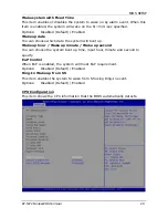
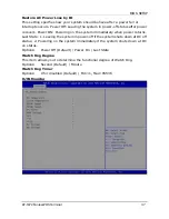
Wake system with Fixed Time 
This item enables or disables the system to wake on by alarm event. When this 
item is enabled, the system will wake on the hr::min::sec specified. 
Options:    Disabled (Default) / Enabled 
Wake up date 
You can choose which date the system will boot up. 
Wake up hour / Wake up minute / Wake up second 
You can choose the system boot up time, input hour, minute and second to 
specify. 
EuP Control 
When EuP is enabled, the system will meet EuP requirement. 
Options:    Disabled (Default) / Enabled 
Ring-In Wake up from S5 
This item enables the system to wake from S5 using Ring-In event. 
Options:    Disabled (Default) / Enabled 
 
CPU Configuration 
This item shows the CPU information that the BIOS automatically detects. 


Содержание KP-5372

Страница 1: ...http www appostar com KP 5372 Touch POS Terminal User Manual Edition NOV 2012 Version 1 02...

Страница 2: ...let on a circuit different from that to which the receiver is connected Consult the dealer or an experienced radio TV technician for help Declaration of Conformity These devices comply with part 15 of...

Страница 3: ...APPOSTAR reserves the right to make improvements to this publication from time to time in the contents hereof without obligation of the manufacturer to notify any person of such revision or changes Co...

Страница 4: ...aerosol sprayers containing flammable gas inside or around the product 7 Do not allow foreign objects or liquids to enter the product serious damage may result 8 Do not place the product on an unstabl...

Страница 5: ...on 9 2 2 Component Installation 15 CHAPTER 3 Software Installation 17 3 1 Motherboard Driver Installation 17 3 2 Peripheral Device Driver Installation 19 CHAPTER 4 BOARD SETTING 21 4 1 Main Board Jump...

Страница 6: ...built u y The ve uished for prevents n The KP ch with th ing items act the de 2 Quick 5 vervie 2 is the c demand up in a co rtical bas r its uniqu the syste P 5372 is e tone of s are cont ealer from k...

Страница 7: ...PRODUCT OVERVIEW KP 5372 Fanless POS Terminal 3 1 2 Appearance Front View Rear View MSR cover Customer display cover Cable management cover MSR cover Rear cover 15 LCD touch panel Front panel Base...

Страница 8: ...PRODUCT OVERVIEW 4 KP 5372 Touch POS Terminal Side View Left Side Right Side I O with cover I O without cover...

Страница 9: ...PRODUCT OVERVIEW KP 5372 Fanless POS Terminal 5 1 3 I O Interface...

Страница 10: ...Built in Speaker 1 5W passive stereo speaker x 2 HDMI HDMI for second display USB USB 2 0 A type Connector x 4 Control Interface No Name Description USB USB 2 0 A type Connector HDD LED Indicator Ind...

Страница 11: ...External COM Ports with 5V 12V selectable Cash Drawer Port 1 x RJ11 with DC 12V single dual Keyboard Port 1 x PS 2 Keyboard VGA Port 1 x DB15 VGA 1 x HDMI Audio Jack 1 x Line in 1 x Line out Speaker...

Страница 12: ...ter 90W optional Environment EMC Safety CE FCC Class A Operating Temperature 5 C 40 C Storage Temperature 20 C 60 C Operating Humidity 15 80 RH Storage Humidity 20 90 RH Mechanical Housing Color Cool...

Страница 13: ...d al Insta ic Strip he cover MSR modu ware I are config disconnec llation e Read An o right from the Step ule in pos Instal guration cted to pr er MSR ptional M t left side MSR 2 Connec ition with ll...

Страница 14: ...sn t work properly please refer to CH 6 Troubleshooting 2 1 2 Integrated LCD VFD Customer Display Installation Step 1 Remove the customer display cover on the main unit Step 2 Unfasten 2 thumb screws...

Страница 15: ...Plug the wafer connector to the COM 6 port with DC 5V on the I O board as shown in the picture Figure 2 f Figure 2 d Figure 2 e Figure 2 f Figure 2 g Step 4 Cover the screw holes with plastic lids and...

Страница 16: ...tal position Figure 3 a Step 2 Remove the cable management and the customer display covers on the main unit Unfasten the 2 thumb screws off both the front and rear cover of the main unit Figure 3 b 3...

Страница 17: ...su Figure 3 ure 3 f p hinge co er hinge c 3 j gure 3 i ith 4 scre ure that t g over and t cover to th Fi ws Fit th the 4 con the upper he second igure 3 he second nection p r hinge co d display a h H...

Страница 18: ...3 l 3 m Fig TION cond disp eshooting ATION he VGA ca r output he front gure 3 l play does g ble to the DC jack the rear n t work Fi e VGA por Figure and the properly igure 3 rt DB15 3 k cable ma pleas...

Страница 19: ...he 2 thum b t the SATA thumb sc ure 4 c 4 screws f w one allation HDD panel to it mb screw TA 1 and S rew that from the Fi Fi n ts horizon ws off the SATA pow holds the HDD brac igure 4 igure 4 ntal p...

Страница 20: ...f the main unit Figure 4 e 4 f Figure 4 e Figure 4 f 2 2 2 Mini PCI Express Card Installation Step 1 Unfasten 2 thumb screws off the rear cover by a coin Figure 5 a 5 b Figure 5 a Figure 5 b Step 2 Lo...

Страница 21: ...drive Windows will automatically detect it and the Appostar Driver Installer appears on the screen If not locate the Setup exe file at CD and double click it to execute the one step driver installati...

Страница 22: ...les to install f After Chipset Driver INF installed click No to continue g Select Install this driver software anyway in Windows Security window to continue the installation procedure h Select Install...

Страница 23: ...n a Click Touch Panel b Click Next on the Welcome screen to continue c Uncheck the Install PS 2 interface driver option Click Next to continue d Select the Install RS232 interface driver option Click...

Страница 24: ...Terminal continue g Select the Destination Folder or use the default one listed h Type a Folder name or use the default one listed Click Next to continue i A progress window appears Please wait j Clic...

Страница 25: ...o Pin 2 3 close 3 Wait for five seconds 4 Set the jumper to Pin 1 2 close 5 Power on the AC 6 Reset your desired password or clear the CMOS data Voltage Switch Header JPC1 JPC6 by jumper select This h...

Страница 26: ...minal 4 2 Port Definition for Cash Drawer Pin Define Status Pin Control Pin GPIO ADD 1 CASE OPEN 2 CASE OPEN 2 63 A25H bit3 2 CASH1_P CASH1_P 14 A20H bit4 3 CASE OPEN CASE OPEN 64 A25H bit4 4 CASH_PWR...

Страница 27: ...fine tuning options are also included in BIOS The rest of this manual will to guide you through the options and settings in BIOS Setup Plug and Play Support This AMI BIOS supports the Plug and Play V...

Страница 28: ...rboard If the system becomes unstable after changing any settings please load the default settings to ensure system s compatibility and stability Use Load Setup Default under the Exit Menu For better...

Страница 29: ...roviding an overview of the basic system information AMI BIOS Shows system information including BIOS version built date etc Total Memory Shows the system memory size VGA shard memory will be excluded...

Страница 30: ...CPU Super I O Power Management and other system devices Notice Beware of that setting inappropriate values in items of this menu may cause system to malfunction Launch Storage OpROM This item allows y...

Страница 31: ...ncy Timer Register Options 32 PCI Bus Clocks Default 64 PCI Bus Clocks 96 PCI Bus Clocks 128 PCI Bus Clocks 160 PCI Bus Clocks 192 PCI Bus Clocks 224 PCI Bus Clocks 248 PCI Bus Clocks VGA Palette Snoo...

Страница 32: ...his option may be not effective with some OS Options Enabled Default Disabled ACPI Sleep State This item selects the highest ACPI sleep state the system will enter when the SUSPEND button is pressed O...

Страница 33: ...e which date the system will boot up Wake up hour Wake up minute Wake up second You can choose the system boot up time input hour minute and second to specify EuP Control When EuP is enabled the syste...

Страница 34: ...ur system from buffer overflow attacks Options Enabled Default Disabled Limit CPUID Maximum When the computer is booted up the operating system executes the CPUID instruction to identify the processor...

Страница 35: ...egacy USB Support This item determines if the BIOS should provide legacy support for USB devices like the keyboard mouse and USB drive This is a useful feature when using such USB devices with operati...

Страница 36: ...Start Unit command time out Options 20 sec Default 10 sec 30 sec 40 sec Device power up delay This is maximum time for the device to take before it properly reports itself to the Host Controller Optio...

Страница 37: ...uiet Aggressive Manual FAN Ctrl OFF When temperature is lower than this value the fan will keep lowest RPM FAN Ctrl ON When temperature is higher than this value the fan controller will turn on FAN Ct...

Страница 38: ...bles Serial Port COM Options Enabled Default Disabled Change Settings This item allows you to select an optimal setting for Super IO device Options Auto Default IO 3F8h IRQ 4 IO 3F8h IRQ 3 4 5 6 7 9 1...

Страница 39: ...ables Serial Port COM Options Enabled Default Disabled Change Settings This item allows you to select an optimal setting for Super IO device Options Auto Default IO 2F8h IRQ 3 IO 3F8h IRQ 3 4 5 6 7 9...

Страница 40: ...ptions Auto Default IO 378h IRQ 7 IO 378h IRQ 6 7 9 10 11 12 IO 278h IRQ 6 7 9 10 11 12 IO 3BCh IRQ 6 7 9 10 11 12 Device Mode This item allows you to determine how the parallel port should function O...

Страница 41: ...ng on the system immediately when power returns Last State 1 Leaving the system in power off if the system shuts down at DC off status 2 Powering on the system immediately if the system shuts down at...

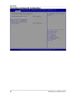
Страница 42: ...BIOS SETUP 38 KP 5372 Touch POS Terminal F81216 Second Super IO Configuration...

Страница 43: ...figuration Serial Port This item enables or disables Serial Port COM Options Enabled Default Disabled Change Settings This item allows you to select an optimal setting for Super IO device Options IO 3...

Страница 44: ...iguration Serial Port This item enables or disables Serial Port COM Options Enabled Default Disabled Change Settings This item allows you to select an optimal setting for Super IO device Options IO 2E...

Страница 45: ...figuration Serial Port This item enables or disables Serial Port COM Options Enabled Default Disabled Change Settings This item allows you to select an optimal setting for Super IO device Options IO 2...

Страница 46: ...ptions Enabled Default Disabled Change Settings This item allows you to select an optimal setting for Super IO device Options IO 2E0h IRQ 5 Default IO 3E8h IRQ 5 IO 2E8h IRQ 5 IO 2F0h IRQ 5 UART IRQ M...

Страница 47: ...bus system PCI or Personal Computer Interconnect is a system which allows I O devices to operate at speeds nearing the speed of the CPU itself uses when communicating with its own special components N...

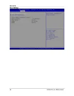
Страница 48: ...BIOS SETUP 44 KP 5372 Touch POS Terminal Host Bridge...

Страница 49: ...sables MRC fast boot Options Enabled Default Disabled Max TOLUD This item sets maximum value of TOLUD Dynamic assignment would adjust TOLUD automatically based on largest MMIO length of installed grap...

Страница 50: ...esent Options D SUB LVDS D SUB LVDS Default HDMI D SUB HDMI LVDS HDMI LCD Panel Type This item selects the LCD panel used by Internal Graphics Device by selecting the appropriate setup item Options 10...

Страница 51: ...he Active LVDS Configuration No LVDS VBIOS does not enable LVDS Int LVDS VBIOS enables LVDS driver by Integrated encoder Options Int LVDS Default No LVDS Fixed Graphics Memory Size This item configure...

Страница 52: ...ent capability of Audio Controller Options Disabled Default Enabled Azalia Vci Enable Azalia supports 1 extended VC which will override ICH VCp settings when enabled Options Enabled Default Disabled S...

Страница 53: ...us Default Quiet Onboard PCIE LAN1 This item enables or disables Onboard PCIE LAN1 Options Auto Default Disabled Enabled Onboard PCIE LAN1 OpROM This item enables or disables the Boot Option for Legac...

Страница 54: ...e system has been switched on Options On Default Off Full Screen LOGO Disaply This item allows you to enable or disable Full Screen LOGO Show function Options Disabled Enabled Default GateA20 Active U...

Страница 55: ...UEFI Boot This item enables or disables boot from the UEFI Devices Options Disabled Default Enabled Boot Option Priorities Items in this sub menu specify the boot device priority sequence from the ava...

Страница 56: ...P 5372 Touch POS Terminal 5 5 SECURITY MENU This menu allows you to provide revise supervisor and user password Administrator Password This item sets Administrator Password User Password This item set...

Страница 57: ...on all changes made during the current session and exit setup Save Changes and Reset Reset the system after saving the changes Restore Defaults This selection allows you to reload the BIOS when proble...

Страница 58: ...system is in 5V standby reset the system If the problem remains unsolved contact your dealer for further assistance The Touch Panel is not working properly 1 Check whether the Touch Panel driver has b...

Страница 59: ...BOOT DISPLAY Device is preset to VGA LVDS as factory default 4 Check the Display Setting 1 Right click on the desktop and click Properties 2 Select the Settings tab and you will see monitor 1 and moni...

Страница 60: ...TROUBLESHOOTING 56 KP 5372 Touch POS Terminal...

Отзывы: