


BOARD SETTING
KP-5372 Fanless POS Terminal
21
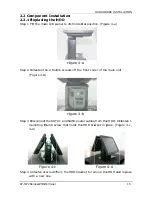
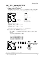
CHAPTER 4 BOARD SETTING
4.1 Main Board Jumper Setting
JCMOS1: Clear CMOS Header *
Placing the jumper on pin2-3 allows user to restore the BIOS safe setting
and the CMOS data. Please carefully follow the procedures to avoid
damaging the mainboard.
3
1
Pin 1-2 Close:
(Default)
Normal Operation.
3
1
Pin 2-3 Close:
Clear CMOS data.
※
Clear CMOS Procedures:
1.
Remove AC power line.
2.
Set the jumper to “Pin 2-3 close”.
3.
Wait for five seconds.
4.
Set the jumper to “Pin 1-2 close”.
5.
Power on the AC.
6.
Reset your desired password or clear the CMOS data.
Voltage Switch Header (JPC1~JPC6) by jumper select
This header is for controlling the Pin9 of COM ports to switch Ring/
5V/12V.
JPC1:
Voltage
Switch
Header
for
JCOM1A
JPC2:
Voltage
Switch
Header
for
JCOM1B
JPC3:
Voltage
Switch
Header
for
JCOM3
JPC4:
Voltage
Switch
Header
for
JCOM4
JPC5:
Voltage
Switch
Header
for
JCOM5
JPC6:
Voltage
Switch
Header
for
JCOM6
2
1
Pin 1-2 Close:
Pin9=5V
6
5
Pin 5-6 Close:
Pin9=12V
4
3
Pin 3-4 Close:
Pin9=Ring
(Default)
Remark:
Max output: 12V@500mA for each COM port
Содержание KP-5372
Страница 1: ...http www appostar com KP 5372 Touch POS Terminal User Manual Edition NOV 2012 Version 1 02...
Страница 9: ...PRODUCT OVERVIEW KP 5372 Fanless POS Terminal 5 1 3 I O Interface...
Страница 42: ...BIOS SETUP 38 KP 5372 Touch POS Terminal F81216 Second Super IO Configuration...
Страница 48: ...BIOS SETUP 44 KP 5372 Touch POS Terminal Host Bridge...
Страница 60: ...TROUBLESHOOTING 56 KP 5372 Touch POS Terminal...


