


24
STF-R/C/D/IP Hardware Manual
920-0141 Rev. A
6/5/2018
3.1 Digital Inputs
3.1.1 X1, X2, X3, X4 digital input signal
X1, X2: optically isolated, differential, 5-24VDC, minimum pulse width 250ns, maximum pulse frequency 2MHz
X3, X4: optically isolated, differential, 5-24VDC, minimum pulse width 100μs, maximum pulse frequency 5KHz
* X1 can be used as general purpose input.
* X2 can be used as general purpose input.
* X3 can be used as CW limit input or general purpose input.
* X4 can be used as CCW limit input or general purpose input.
Please use STF Configurator software for X1,X2,X3 and X4 function configuration.
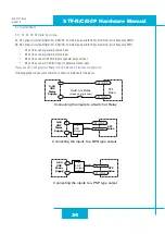
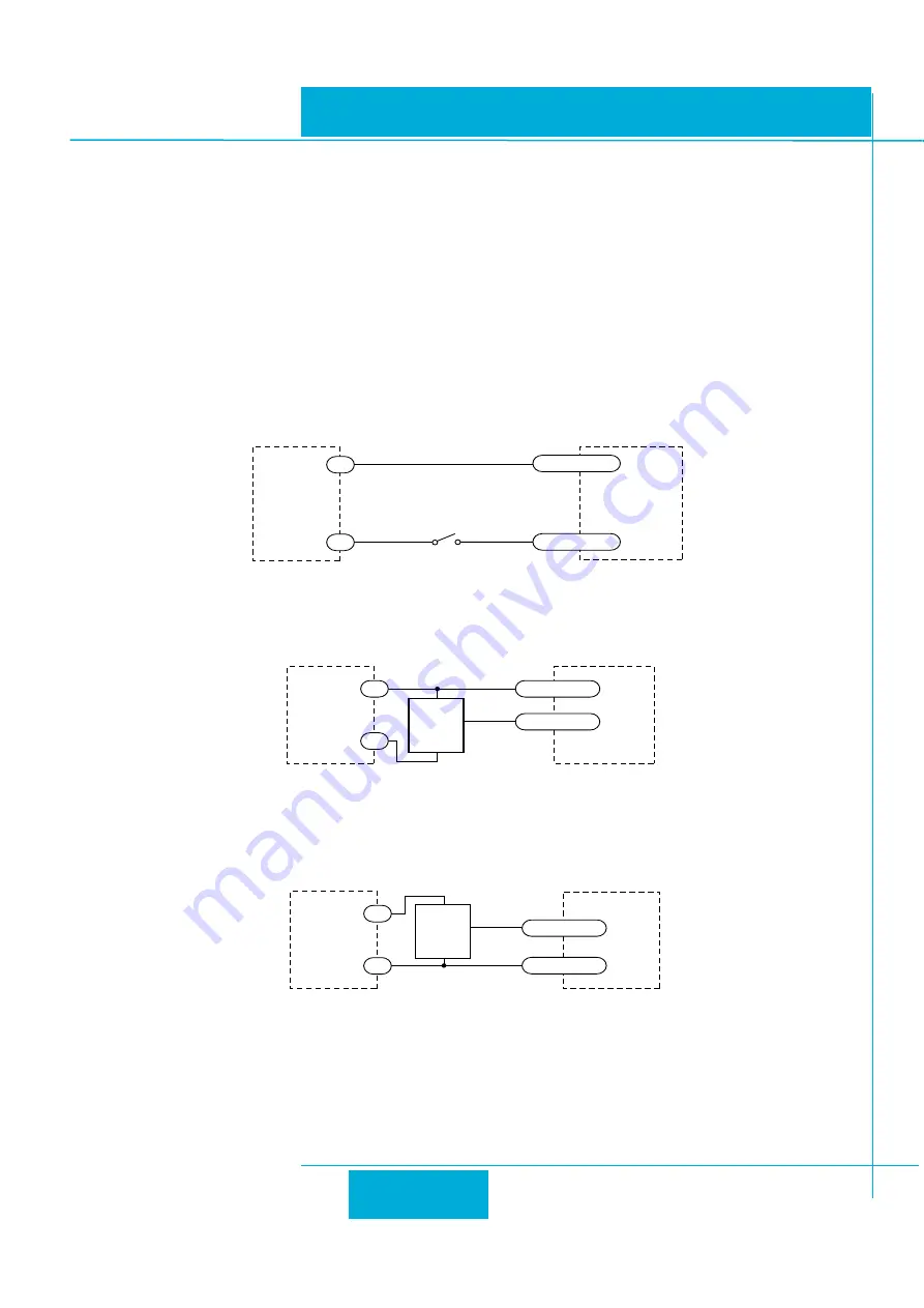
Following graphs shows some common connection methods for the inputs:
STF
Drive
Switch or Relay
(closed = logic Low)
X1/2/3/4-
X1/2/3/4+
-
+
5-24
VDC
Power
Supply
STF
Drive
NPN
Output
X1/2/3/4-
X1/2/3/4+
output
+
–
5-24
VDC
Power
Supply
-
+
STF
Drive
PNP
Output
X1/2/3/4+
output
+
–
X1/2/3/4-
5-24
VDC
Power
Supply
-
+
Connecting the inputs to a Switch or Relay
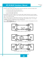
Connecting the inputs to a NPN type output
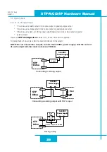
Connecting the inputs to a PNP type output


