background image


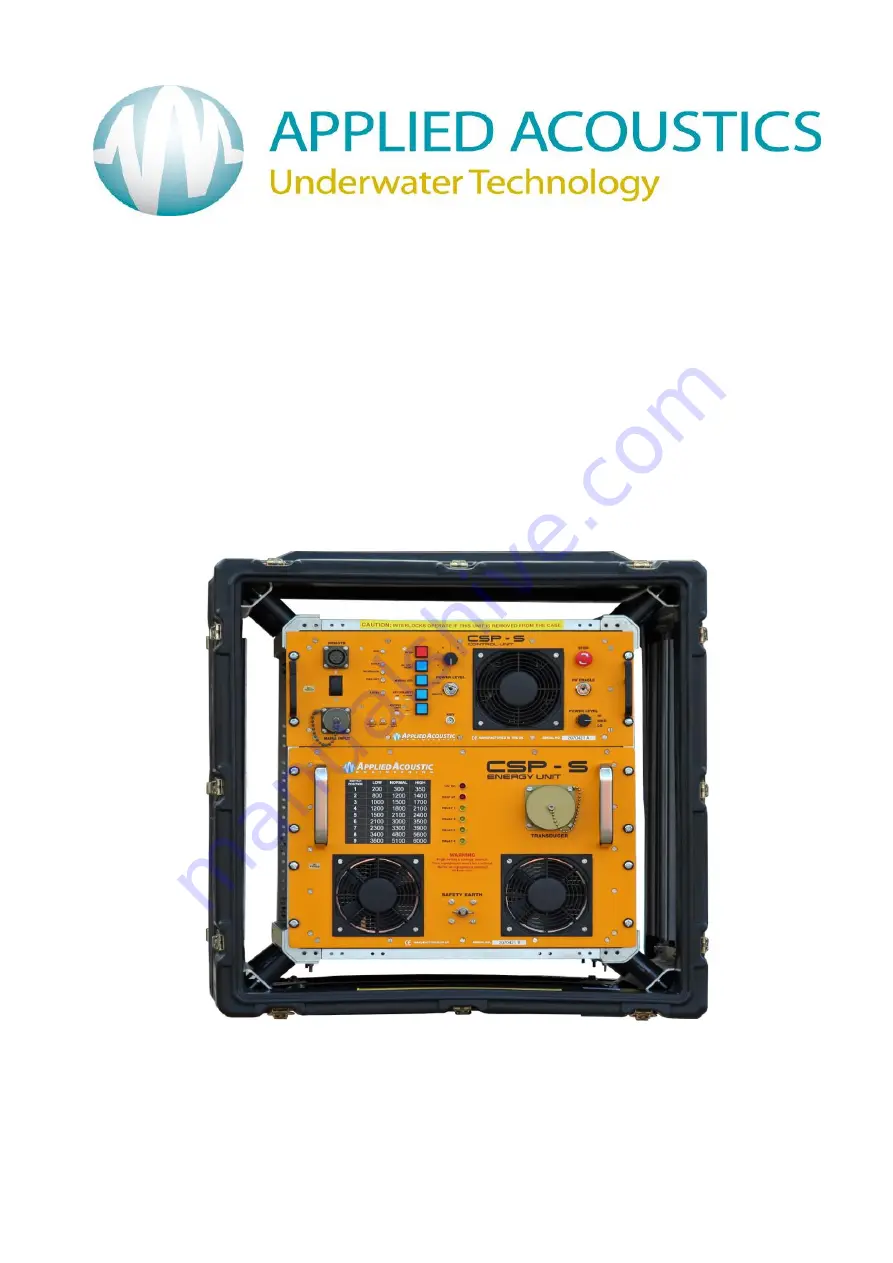
CAPACITOR CHARGING UNIT 


CSP-CSPS-8000/B 


MODELS COVERED IN THIS MANUAL: 


CSP-S    4000 


CSP-S   6000 


 ISSUE B JUNE 2009

Содержание CSP-S 4000

Страница 1: ...CAPACITOR CHARGING UNIT CSP CSPS 8000 B MODELS COVERED IN THIS MANUAL CSP S 4000 CSP S 6000 ISSUE B JUNE 2009 ...

Страница 2: ...CSP CSPS 8000 B Section 1 Page 2 of 30 ...

Страница 3: ...CSP CSPS 8000 B Section 1 Page 3 of 30 OPERATION MANUAL Section 1 ...

Страница 4: ...CSP CSPS 8000 B Section 1 Page 4 of 30 ...

Страница 5: ...B Section 1 Page 5 of 30 CONTENTS PAGE 1 Enviormental Considerations 9 2 Introduction 10 2 Installation 11 3 Operation 18 4 Operator Controls and Indicators 23 5 End of Life Recycling Disposal 27 6 Specifications 28 ...

Страница 6: ...CSP CSPS 8000 B Section 1 Page 6 of 30 ...

Страница 7: ...ration than the agreement and condition that it is not to be reproduced copied or otherwise disposed of directly and is not to be used in whole or in part to assist in or to furnish any information for the making of drawings prints apparatus or parts thereof THIS EQUIPMENT CONTAINS LETHAL VOLTAGES AND MUST BE EARTHED AT ALL TIMES ENSURE ADEQUATE SAFETY PROCEDURES ARE EMPLOYED ...

Страница 8: ...CSP CSPS 8000 B Section 1 Page 8 of 30 ...

Страница 9: ...y to escape before maximum signal amplitude is reached It will also give them a chance to get used to the noise if they choose to stay rather than being subjected to a sudden shock of a full power seismic signal Another factor to consider is to ensure that the start of any survey line is not in such a location that any cetacian is trapped by the vessel and the noise for example in a small harbour ...

Страница 10: ...CSP CSPS 8000 B Section 1 Page 10 of 30 ...

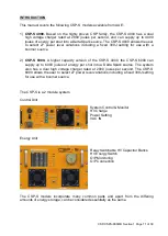
Страница 11: ...gher capacity version of the CSP S 4000 the CSP S 6000 can supply up to 6000 joules of energy per shot into a Delta Spark source The system also has a dual high voltage charger rated at 2800 joules per second The CSP S 6000 allows the user to select 27 power level variations including a fixed 300J setting for use with a boomer source The CSP S is a 2 module system Control Unit System Control Monit...

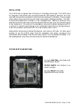
Страница 12: ...ent the CSP S must be located away from water spray and condensation in an environment which is not allowed to become too hot Care should be taken to allow safe and easy access and that high voltage cables are out of harms way It should also be possible to switch off the unit quickly without having to reach over it Ventilation should also be present All units draw air in from the rear and exhaust ...

Страница 13: ...etal cutting gear can cause damage which may result in the equipment becoming unsafe from having an ineffective earth The CSP S range of Capacitor Discharge PSUs are compact and easy to operate However the units still generate lethal voltages and the operators should make themselves aware of all necessary safety procedures The equipment is designed so that there is no need for the operator to go i...

Страница 14: ...rom the rear panel to any obstruction If the unit is to be operated in very warm ambient temperature 25 C or above for optimum performance an air conditioned environment is strongly advised If the unit overheats it will switch OFF for a few minutes until it is cool Although the unit produces minimal interference and carries a CE mark it is often good practice to put the CSP S away from the navigat...

Страница 15: ... place Ensure the HV connector is fully mated to the unit The two larger sockets should never be at a high potential but it makes sense never to attempt to touch these If you have our HV junction box the two conductors of the acoustic source boomer plate or sparker should be connected to this before connecting to the CSP S The terminal wing nuts should be tightened onto clean copper or tinned copp...

Страница 16: ...llowing colour coding Green yellow Earth Blue Neutral Brown Live The operator must ensure that the ac supply is capable of supplying sufficient energy to power the CSP S unit Although the unit will operate from most generators of 8 kVA the quality and regulation vary considerably from make to make and how well they have been maintained A voltage stabiliser is not necessary as any reasonable variat...

Страница 17: ...pacitors reduces with reduced line voltage as the following tables apply 240 V Models Line Voltage Charge Rate 180 VAC 2500 J second 200 VAC 2800 J second 210 VAC 3000 J second 115 V models Line Voltage Charge Rate 100 115 VAC 2600 J second 116 130 VAC 3000 J second You may notice that the low line voltages above are below those specified in the rear of this manual under specifications The above t...

Страница 18: ...o a warm one condensation may have developed which may cause arcing in high voltage equipment The operator is advised to switch the unit on and run the fans for 10 15 minutes before allowing the high voltage to be switched on This will allow the unit to warm up to the room temperature and any condensation will disperse ...

Страница 19: ...changes in system parameters such as power change will cause the HV to switch OFF and the unit will need to be RESET before the HV can be switched on again If the INTERLOCK indicator illuminates check the HV plug HV junction box Trigger Input Trigger input is by BNC connector The unit accepts ve trigger triggers on rising edge 5 20 volts opto isolated or by contact closure as controlled by the KEY...

Страница 20: ... 5 clicks will be heard depending on the energy selected as the relays switch in circuit Once these relays have engaged the high voltage is enabled If the 1 9 power level switch is moved or if the HV off reset button is pressed the unit will shut down safely In an emergency the red STOP button can be pressed The maximum repetition rate is governed by the charge rate 2800 Joules per second and the ...

Страница 21: ...S The LO voltage setting achieves this so for example using an AA300 boomer plate at 200J at 3 pulses per second may be a common way of using the transducer with the traditional 3 5 kV supply voltage Load Specifications The CSP S units are designed to deliver high currents into boomer or sparker type loads The loads are quite different in make up Boomer Load A boomer plate consists of a coil imbed...

Страница 22: ...y of the water Typical values are shown below for AAE sparkers in standard seawater with a salinity of 35 ppm Energy Squid 500 60 tips Squid 2000 120 tips DELTA Spark 6 Tips 100J 1000A 1900A N A 600J 1300A 2800A N A 1500J 1300A 3000A 2600A 2000J N A 3300A 2800A 3000J N A N A 3200A 4000J N A N A 3500A 5000J N A N A 3750A 6000J N A N A 4000A Dummy Load AAE manufacture a dummy load with precisely des...

Страница 23: ...ys on switching switch illuminates when the high voltage is switched on operated in conjunction with the HV ENABLE key switch thus to switch HV ON HV ENABLE needs to be enabled simultaneously MANUAL KEY switch Triggers CSP unit when pressed Also illuminates when an external key pulse is detected KEY POLARITY switch Used to select either ve key pulse 3 5 20 volts opto isolated triggers 0 5 mS from ...

Страница 24: ...unit is powered up and will extinguish when the RESET button is pressed It will otherwise illuminate during most faults Please note that the fault light will not illuminate if the thermal cut out operates in the charger module INTERLOCK indicator Illuminated if front panel connector is left out when the unit is switched ON or if the lid of the HV junction box has not been closed correctly The inte...

Страница 25: ... INTERLOCK fault TRIGGER INPUT The trigger input is connected via a BNC socket REAR PANEL FUSES The rear panel contains 2 fuse holders and these are the only things we recommend the operator checks if he has not received factory training The fuses are rated as follows CONTROL UNIT F1 3A Antisurge 1 240V 7A Antisurge 1 110V F2 3A Antisurge 1 240V 7A Antisurge 1 110V ENERGY UNIT F3 3A Antisurge 1 24...

Страница 26: ...it cannot be stressed enough that the operator and all those who might come into contact with this equipment treat it with extreme caution and should not take any safety feature for granted The unit should be disabled by removal of the key switch or removal of the mains lead or the HV Plug before any attempt is made to make any wiring changes or inspection of the load Despite being heavily insulat...

Страница 27: ...ves Applied Acoustics as a manufacturer within the EU will responsibly dispose of any returned end of life Applied Acoustics components batteries through a registered WEEE scheme In order to prevent uncontrolled waste disposal and promote re cycling please return any end of life Applied Acoustic components postage paid by sender to our UK head office Please contact Tech Support for a RMA number pr...

Страница 28: ...trical Specifications Mains Input 207 260 V 1 phase 45 65 Hz 6 kVA 3 Pin connector Voltage Output 2500 to 4000 volts DC Output Power 300 to 6000J depending on model By 4 Pin connector Power and interlock Selection Rotary switches Trigger ve key 5 to 25V rising edge opto isolated or contact closure Set by front panel switch Discharge Method Semiconductor module Remote 10 way amphenol Earth M8 stain...

Страница 29: ...fter fault or if interlock activated Keyswitch Must be rotated to enable high voltage Switch can be removed to disable unit for example when working on deck Open circuit detect Disables firing when an open circuit load is present Thermal shut down HV charger shuts down if it overheats Options Remote Allows operator to control unit at a distance Includes key pulse line Junction Box For connection o...

Страница 30: ...1 Page 30 of 30 Applied Acoustic Engineering Ltd Marine House Marine Park Gapton Hall Road Great Yarmouth NR31 0NL UK Phone 44 0 1493 440355 Fax 44 0 1493 440720 E mail techsupport appliedacoustics com www appliedacoustics com ...

Отзывы: